
Foundation near foundation pit slope and reinforcement method thereof

A foundation reinforcement and foundation pit edge technology, applied in excavation, infrastructure engineering, construction, etc., can solve safety problems, self-heavy, unsafe slopes, etc.

Inactive Publication Date: 2015-06-17
CHINA NUCLEAR IND FIFTH CONSTR CO LTD
View PDF5 Cites 9 Cited by
  • Summary
  • Abstract
  • Description
  • Claims
  • Application Information

AI Technical Summary

Problems solved by technology

[0004] With the development of industry, many projects currently require negative excavation of foundation pits, and then related building construction. When excavating foundation pits, it is necessary to use large-scale hoisting machinery to hoist the internal equipment of the building, but it is limited to the hoisting performance of the hoisting machinery. Hoisting machinery It needs to be close to the edge of the slope of the foundation pit. Because the hoisting machine has a very heavy weight when hoisting, especially in the face of modern buildings, the hoisting machine often weighs several thousand tons, which makes the slope extremely unsafe. Therefore, it is necessary to invent a hoisting machine close to the slope. Safe foundation reinforcement measures for deep foundation pit slopes, so as to ensure safe lifting process
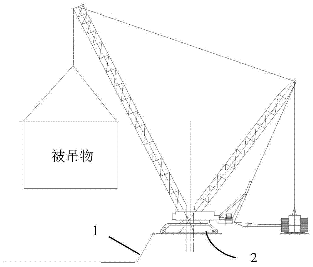
The schematic diagram of hoisting machinery close to the slope of the foundation pit is as follows: figure 1 As shown, the distance between the crawler edge of the hoisting machine and the side slope is about 0.25m. The weight of the hoisted object is several thousand tons, and the height of the side slope is about 10m. If the foundation is not handled properly, there will be safety problems

Method used


Image

  • Foundation near foundation pit slope and reinforcement method thereof
  • Foundation near foundation pit slope and reinforcement method thereof
  • Foundation near foundation pit slope and reinforcement method thereof

Examples


Embodiment Construction

[0024] The present invention is aimed at the overall reinforcement of the hoisting foundation when the hoisting machine is close to the side slope of the excavated foundation pit, which includes the use of micro piles for reinforcement at the crane station site, the reinforcement of the foundation pit side slope area of ​​the hoisting site, and the concrete in the walking area of ​​the crane. Pouring, so that the crane station point and the overall layout of the walking area form an overall reinforcement, thereby ensuring the safety of the crane station on the edge of the foundation pit.

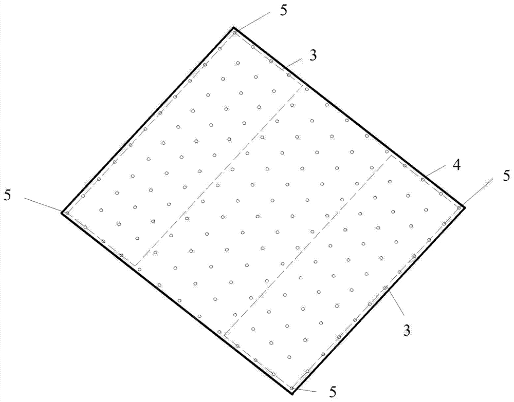
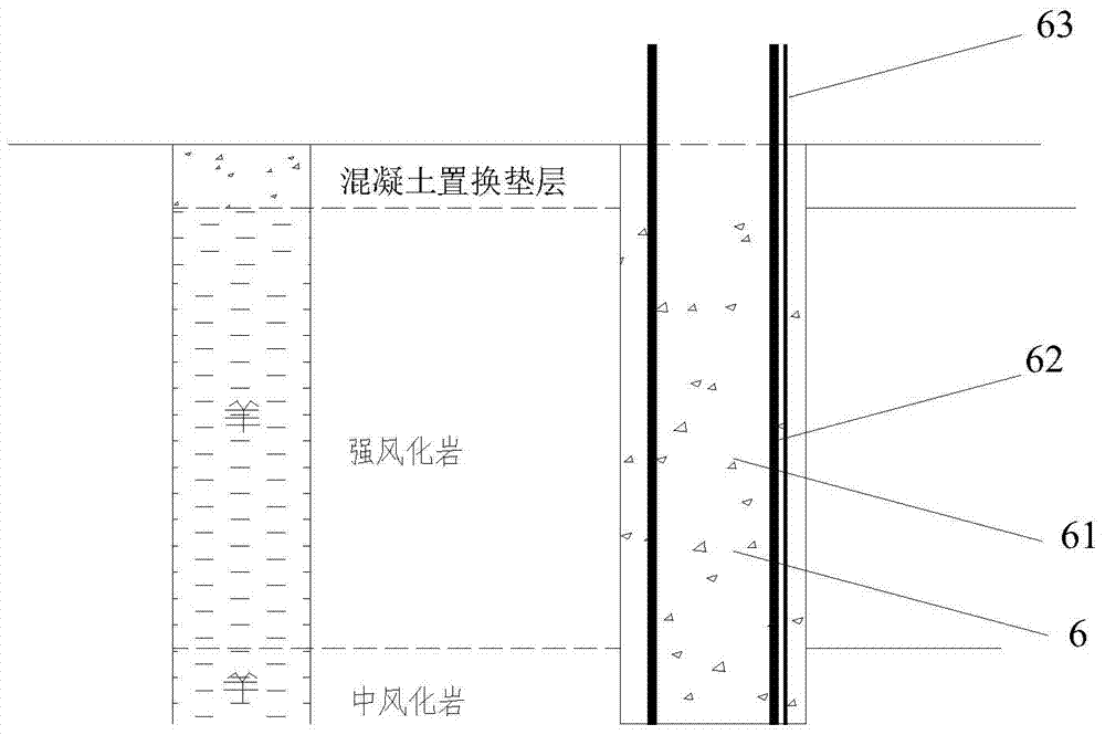
[0025] The crane station point is reinforced by micro piles, such as figure 2 , image 3 , Figure 4 As shown, including the use of hole-forming equipment to carry out the construction of strong micro-steel piles at the reinforcement points of the hoisting site. In the embodiment of the present invention, the horizontal spacing of the miniature steel piles 6 is 1.6m, the diameter of the h...


PUM


Abstract

The invention discloses a foundation near a foundation pit slope and a reinforcement method thereof, is a safe foundation reinforcement measure when a lifting machine is near a deep foundation pit slope, and guarantees safe implementation of the lifting process. A crane station site is reinforced by a micro pile; hole forming equipment is used for forming a hole in a lifting reinforcement point of the lifting station site; a micro steel pile is put into the hole; then, the normal-pressure grouting is performed; after a pile body is formed to a pile, the high-pressure grouting is performed through a high-pressure grouting pipe attached on the micro steel pile; and finally, the crane station site is cast by concrete. A lifting field foundation pit slope area is reinforced by an anchor rod; a long rock anchor rod is arranged at the intense weathering part at the upper part of the slope; a short rock anchor rod is arranged at the weathered rock layer part at the lower part of the slope; a reinforced concrete surface layer is sprayed to the surface of the slope; after holes are formed in the anchor rods, the grouting is performed; a crane belt walkimng area is cast by concrete; filled soils at the upper part of the crane belt walking area are removed to the top surface of the intense weathering rock layer; the concrete is cast to reach the required field height; and an expansion joint and a shrinkage joint on a concrete road surface are arranged.

Description

technical field [0001] The invention relates to a foundation adjacent to a side slope of a foundation pit and a reinforcement method thereof. Background technique [0002] Large crawler cranes are heavy in weight and good in stability. Outriggers may not be used, and they can be used in relatively soft and muddy places. Because of their convenient loading and unloading, large lifting capacity, and strong mobility, they are widely used in power plant construction and water conservancy construction. It is widely used in large-scale projects such as petrochemical industry, port and bridge, and railway loading and unloading. It is an indispensable lifting machinery in current lifting operations. The maximum lifting capacity of the crane is large, and its own weight is also very large. Because the working site of crawler cranes is often transferred, the working environment is quite complicated. There are strict requirements on the longitudinal and horizontal slope of the walking...

Claims


Application Information

Patent Timeline
IPC IPC(8): E02D17/20E02D17/04
CPCE02D17/04
Inventor 王树昂魏焕卫
Owner CHINA NUCLEAR IND FIFTH CONSTR CO LTD
Learn More