Wavelength division multiplexer and optical module

A technology of wavelength division multiplexer and light guide block, which is applied in the field of optical communication, can solve the problems of low reliability of wavelength division multiplexer, large beam offset, unstable beam, etc., and achieves easy packaging, stable optical path, The effect of improving stability

Inactive Publication Date: 2015-06-17
HISENSE BROADBAND MULTIMEDIA TECH
View PDF3 Cites 4 Cited by
  • Summary
  • Abstract
  • Description
  • Claims
  • Application Information

AI Technical Summary

Problems solved by technology

However, the number of reflections of the four wavelength beams during transmission is different (up to six reflections), so that the optical path of each wavelength beam is different, and is affected by the position angle of the laser chip, collimator lens and diaphragm (such as offset due to thermal expansion), too many beam reflections will cause excessive beam offset, resulting in unstable beams, resulting in lower reliability of the wavelength division multiplexer

Method used


Image

  • Wavelength division multiplexer and optical module
  • Wavelength division multiplexer and optical module
  • Wavelength division multiplexer and optical module

Examples


Embodiment 1

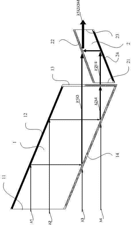
[0021] Such as figure 2 As shown, the wavelength division multiplexer in this embodiment includes a first light guide block 1 and a second light guide block 2, and the side wall of the first light guide block 1 forms a first light surface 11, a second light surface 11, and a second light guide block that are connected in sequence. Two light surfaces 12, a third light surface 13 and a fourth light surface 14, the side walls of the second light guide block 2 form a light surface one 21, a light surface two 22, a light surface three 23 and a light surface four connected in sequence 24. The optical surface one 21 is located on one side of the third optical surface 13; the first optical surface 11 has an anti-reflection coating layer, the second optical surface 12 has a reflective coating layer, and the second optical surface 12 has a reflective coating layer. An anti-reflection film layer and a half-wave plate are sequentially arranged on the three optical surfaces 13 along the l...

Embodiment 2

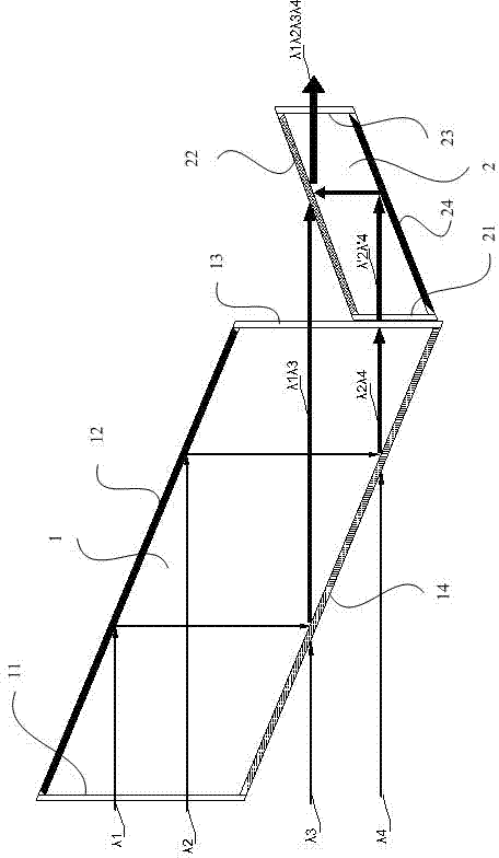
[0026] Such as image 3As shown, the wavelength division multiplexer of this embodiment is based on the above-mentioned embodiment, and the difference from the above-mentioned embodiment is that there is only an anti-reflection coating layer on the third optical surface 13 without a half-wave plate, and the optical surface-21 is set There are half wave plates.

[0027] Specifically, the wavelength division multiplexer of this embodiment is provided with a half-wave plate on the optical surface 21. After the light beam of λ2λ4 enters the optical surface 21, it passes through the action of the half-wave plate, so that the light beam of λ2λ4 is polarized by P The light becomes S polarized light. The specific process is as follows: the light beams of λ1 and λ2 are vertically incident on the first light surface 11 of the first light guide block 1 coated (or pasted) with the AR anti-reflection film layer, and are respectively transmitted to the second light surface 12 by the second...

Embodiment 3

[0029] According to design requirements, the first smooth surface 11, the second smooth surface 12, the third smooth surface 13 and the fourth smooth surface 14 can be distributed clockwise or counterclockwise. Similarly, smooth surface one 21, smooth surface two 22, smooth surface Three 23 and smooth four 24 can also be distributed clockwise or counterclockwise. Such as figure 2 As shown, the first light surface 11, the second light surface 12, the third light surface 13 and the fourth light surface 14 are distributed in a clockwise direction. Similarly, as image 3 As shown, smooth surface 1 21 , smooth surface 2 22 , smooth surface 3 23 and smooth surface 4 24 can also be distributed in a clockwise direction.

[0030] Preferably, in order to facilitate clamping and assembly, there is a prism (not shown) covering the polarization multiplexing film layer on the optical surface 22. The prism can be a triangular structure, and one surface of the prism is connected to the opti...


PUM


Abstract

The invention provides a wavelength division multiplexer and an optical module. The wavelength division multiplexer comprises a first light guiding block and a second light guiding block, wherein the side walls of the first light guiding block form a first optical surface, a second optical surface, a third optical surface and a fourth optical surface which are sequentially connected in an encircled manner, the side walls of the second light guide block form an optical surface I, an optical surface II, an optical surface III, and an optical surface IV which are sequentially connected in an encircled manner, and the optical surface I is located on one side of the third optical surface; the first optical surface is provided with an antireflection film layer, the second optical surface is provided with a reflection film layer, the third optical surface is sequentially provided with an antireflection film layer and a half wavelength plate along the length direction, and the fourth optical surface is sequentially provided with a first thin-film smoothing film layer and a second thin-film smoothing film layer along the length direction; the optical surface I and the optical surface III are respectively provided with an antireflection film layer, the optical surface II is provided with a polarization wave combination film layer, and the optical surface IV is provided with a reflection film layer. The stability of the wavelength division multiplexer is enhanced.

Description

technical field [0001] The invention relates to the technical field of optical communication, in particular to a wavelength division multiplexer and an optical module. Background technique [0002] With the increasingly higher requirements for communication bandwidth in the field of optical fiber communication, global optical communication is currently in a period of rapid development. In the field of high-speed data communication, due to the speed bottleneck of electrical transmission, for optical fiber communication networks with a transmission rate of 40 / 100Gbps, in order to ensure long-distance high-speed transmission of data, optical modules (optical transmission modules) are usually used in the prior art and optical receiving module) to realize the transmission and reception of different wavelengths of light. The commonly used solution is to multiplex 4 channels of optical signals of different wavelengths into a single-mode fiber for transmission. The optical signal ...

Claims


Application Information

Patent Timeline
Patent Type & Authority Applications(China)
IPC IPC(8): G02B6/293G02B6/34
CPCG02B6/293G02B6/34G02B27/283
Inventor 陈思乡
Owner HISENSE BROADBAND MULTIMEDIA TECH
Why Eureka
Try Eureka