Organic electroluminescence device and preparing method thereof

An electroluminescent device, organic technology, applied in the direction of organic light-emitting devices, organic light-emitting device parameters, electro-solid devices, etc.

Active Publication Date: 2015-06-17
BEIJING VISIONOX TECH +1
View PDF3 Cites 38 Cited by
  • Summary
  • Abstract
  • Description
  • Claims
  • Application Information

AI Technical Summary

Problems solved by technology

The researchers proposed to use triplet state quenching to generate singlet states in fluorescent devices to improve the efficiency of fluorescent de

Method used


Image

  • Organic electroluminescence device and preparing method thereof
  • Organic electroluminescence device and preparing method thereof
  • Organic electroluminescence device and preparing method thereof

Examples


Embodiment 1

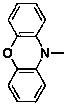
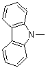
[0251] In this example, yellow light-emitting devices with different doping concentrations of fluorescent dyes were prepared, and these devices have such as image 3 structure shown. The light-emitting layer contains a host material (Host 1) and a fluorescent doped dye (YD 1), in which the Host 1 material is the first type of host material, and the first triplet state of its (n-π) excited state is slightly smaller than that of CT The first triplet state (0.1 eV) of the excited state, the singlet energy level of YD1 is 2.2 eV, which is lower than that of Host 1. The structural formulas of Host 1 and YD 1 are as follows:

[0252] ,

[0253] 2-7, YD1

[0254] The device structure of this embodiment is as follows:

[0255] ITO (150nm) / NPB (40nm) / Host 1: (0.01%, 0.5%, 1.0%, 5%): YD 1 (30nm) / Alq 3 (20nm) / LiF(0.5nm) / Al(150nm)

[0256] Wherein, the percentages in parentheses before YD1 indicate different doping concentrations of fluorescent dyes, an...

Embodiment 2

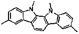
[0275] In this example, red light-emitting devices with different doping concentrations of fluorescent dyes were prepared, and these devices had such image 3 structure shown. The light-emitting layer contains a host material (Host2) and a fluorescent dopant dye (RD 1). The energy level difference between the triplet state of the CT excited state of Host2 and the triplet state of the (n-π) excited state is very large (1.3 eV), and the second triplet state of the (n-π) excited state is higher than the first triplet state of the CT excited state. A singlet state, the singlet energy level of RD1 is 2.0 eV, and the singlet energy level of RD1 is lower than that of Host 2. The structural formulas of Host 2 and RD1 are as follows:

[0276] ,

[0277] 3-6, RD1

[0278] Prepare an organic electroluminescence device in the same manner as in Example 1 above, and the structure of the light-emitting device is as follows:

[0279] ITO (150nm) / NPB (40nm) / Host ...

Embodiment 3

[0290] In order to test the influence of the host material of the present invention on the performance of the organic electroluminescent device, this example prepared an organic electroluminescent device in the same manner as in Example 1 above. The structure of the light emitting device is as follows:

[0291] ITO (150nm) / NPB (40nm) / host material: 0.5% YD 1 (30nm) / Bphen (20nm) / LiF (0.5nm) / Al (150nm).

[0292] The properties of the organic electroluminescent device are shown in Table 3 below:

[0293] table 3

[0294] Light-emitting layer structure Current efficiencycd / A OLED3 1-1: (0.5%) YD 1 (30nm) 20 OLED4 1-2: (0.5%) YD 1 (30nm) 24 OLED5 1-3: (0.5%) YD 1 (30nm) 30 OLED6 1-4: (0.5%) YD 1 (30nm) 24 OLED7 1-5: (0.5%) YD 1 (30nm) 34 OLED8 1-6: (0.5%) YD 1 (30nm) 36 OLED9 1-7: (0.5%) YD 1 (30nm) 28 OLED10 1-8: (0.5%) YD 1 (30nm) 31 OLED11 1-9: (0.5%) YD 1 (30nm) 29 OLED12 1-10: (0.5%) ...


PUM


Abstract

An organic electroluminescent device and a method for manufacture thereof. The body material of the light-emitting layer (06) of the organic electroluminescent device is a material that the triplet state energy level of CT excited state is higher than that of n-πexcited state by 0-0.3 eV; Or, the body material of the light-emitting layer (06) is a material that the triplet state energy level of CT excited state is higher than that of n-πexcited state by more than 1.0 eV, and the difference between the second triplet state energy level of n-π excited state and the first singlet state energy level of CT excited state is -0.1-0.1 eV. A Luminescent dye is a fluorescent dye. The organic electroluminescent device can fully take advantage of the triplet state of the light-emitting layer (06), so the 100% luminescence efficiency of fluorescent device can be obtained, and the use of noble metal is avoided so as to reduce costs.

Description

technical field [0001] The invention belongs to the field of organic electroluminescent devices, and in particular relates to an organic electroluminescent device and a preparation method thereof. Background technique [0002] Under electro-excitation conditions, organic electroluminescent devices will produce 25% singlet states and 75% triplet states. Traditional fluorescent materials can only utilize 25% of the singlet excitons due to spin prohibition, so the external quantum efficiency is only limited to within 5%. Almost all triplet excitons can only be lost as heat. To improve the efficiency of organic electroluminescent devices, triplet excitons must be fully utilized. [0003] In order to utilize triplet excitons, researchers have proposed many methods. Most notable is the utilization of phosphorescent materials. Due to the introduction of heavy atoms, the phosphorescent material has a spin-orbit coupling effect, so it can make full use of 75% of the triplet state...

Claims


Application Information

Patent Timeline
IPC IPC(8): H01L51/52H01L51/54H01L51/56
CPCH10K50/11H10K2101/40H10K71/00C09K11/025C09K11/06H10K85/611H10K2101/00H10K85/624H10K85/633H10K85/656H10K85/6572H10K85/654H10K85/622H10K85/636H10K85/653H10K85/657H10K85/6565H10K50/15H10K50/16H10K85/655H10K2101/10C09K2211/1007C09K2211/1011C09K2211/1029C09K2211/1088
Inventor 邱勇段炼张东东张国辉
Owner BEIJING VISIONOX TECH
Why Eureka
Try Eureka