Thermal electronic surface emitting source for vacuum system

A vacuum system and electronic surface technology, applied in the direction of measurement/testing and testing optical properties in the manufacturing process, can solve the problems of non-uniformity, many centers, and the inability to detect the luminous efficiency and afterglow of the fluorescent screen, etc., and achieve a simple structure , the effect of easy processing

Inactive Publication Date: 2010-03-31
南京理工大学张家港工程院有限公司
View PDF0 Cites 4 Cited by
  • Summary
  • Abstract
  • Description
  • Claims
  • Application Information

AI Technical Summary

Problems solved by technology

Above the thermionic surface emission source, there is a vacuum chamber. In the vacuum chamber, there is a turntable that can place multiple fluorescent screens. During detection, each fluorescent screen to be tested is rotated by the turntable to the high-energy electron bombardment window of the thermionic surface emission source. Above, when the electron emission source is energized, the filament heats up to generate electrons and changes the energy of the electrons in the accelerating electric field to generate high-energy electrons, which bombard the upper fluorescent screen to make it emit light. However, only the first electron emission source is used in the structure of the electron emission source. The anode does not use the second anode to change the electron trajectory, so after the emitted electrons are accelerated by the electric field, only a fixed distribution of high-energy electron beams is formed. This electron beam distribution is usually more in the middle, slightly less at the edge, and not very uniform, such as When visually judging the uniformity of fluorescent screen luminescence, this electron emission source can also meet the detection requirements, but when using high-resolution CCD image acquisition method to judge the uniformity of fluorescent screen luminescence, this uneven electron distribution cannot Produces a uniform high-energy electron beam, so it cannot meet the test accuracy requirements; in addition, the thermionic surface emission source of this equipment cannot complete the convergence and submersion of the high-energy electron beam, so it cannot detect the luminous efficiency and afterglow of the fluorescent screen

Method used


Image

  • Thermal electronic surface emitting source for vacuum system
  • Thermal electronic surface emitting source for vacuum system
  • Thermal electronic surface emitting source for vacuum system

Examples


Embodiment Construction

[0011] The present invention will be described in further detail below in conjunction with the accompanying drawings.

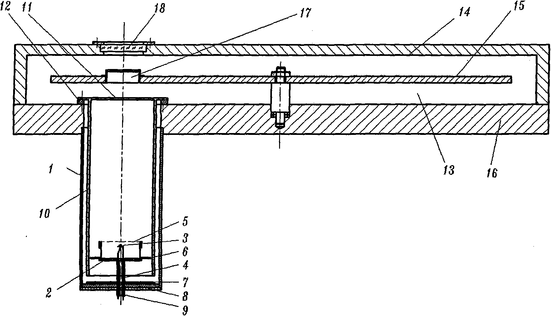
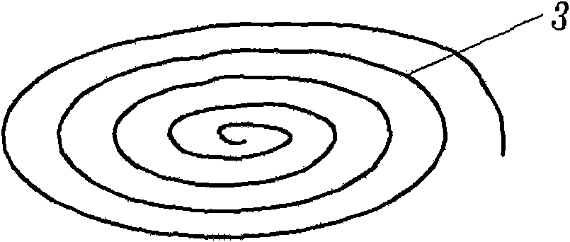
[0012] combine figure 1 , the thermionic surface emission source in the vacuum system that makes according to the present invention, it is made of shell 1, lamp holder 2, filament 3, filament terminal post 4, electron scattering net 5, terminal post frequency shielding disc 6, base frequency shielding disc 7 and a sleeve 10; the material of the shell 1 is stainless steel, the potential is 0V, and it is welded at the test port of the chassis 16 of the vacuum chamber. The bottom cover of the shell 1 is provided with an insulating disc 8, and the base frequency shield is placed on the insulating disc 8. Disc 7, base frequency shielding disc 7 is insulated from the bottom cover of heat shell 1; lamp holder 2 is made of stainless steel, 15mm high, 32mm in diameter, and filament 3 is placed inside. Filament 3 is tantalum wire with a diameter of 0.3mm, according to ...


PUM


Abstract

The invention discloses a thermal electronic surface emitting source for a vacuum system. In the invention, a first anode comprises a lamp holder, a lamp filament, a lamp filament wiring column, an electronic scattering mesh, a wiring column frequency shielding disk and a base frequency shielding disk, and a second anode is formed in such a way that a sleeve is added in a shell of the thermal electronic surface emitting source in a mutually insulating way; by the invention, an electronic track is effectively changed; after emitted electrons are accelerated by an electric field, the distribution of formed high-energy electronic beams can be controlled by changing the potential condition; the lamp filament is wound into a pane spiral shape by a tantalum wire; the lamp filament in the shape can generate the uniform high-energy electronic beams, finish the uniformization, gathering and submerging of the high-energy electronic beams and realize the detection of parameters of a fluorescent screen, such as uniformity, light emitting efficiency, afterglow, and the like; particularly, the detection error of the uniformity is smaller than +/-0.05; and the invention has multiple functions, simple structure and easy processing, can completely meet the test of all the parameters of the fluorescent screen and can be widely used for the quality detection of the fluorescent screens on variousimage intensifiers.

Description

technical field [0001] The invention relates to a thermal electron surface emission source in a micro-optical device parameter testing device, in particular to a vacuum system thermal electron surface emission source capable of providing high-energy uniform electrons. Background technique [0002] The low-light image intensifier is the core component of the night vision device. The fluorescent screen on the image intensifier needs to be inspected and screened before indium sealing, so as to improve the pass rate of the product and reduce the cost. The phosphor screen can only be detected when it emits light. For example, for the uniformity detection of phosphor powder coating, it is necessary to bombard it with uniform high-energy electrons under a certain voltage condition to make it emit light, and then use a high-resolution CCD to collect images. Then use software to analyze its uniformity; to detect the luminous efficiency of the fluorescent screen, it is necessary to ma...

Claims


Application Information

Patent Timeline
Patent Type & Authority Applications(China)
IPC IPC(8): H01J9/42G01M11/02
Inventor 邱亚峰常本康钱芸生富荣国张俊举刘磊陈敏石作伟
Owner 南京理工大学张家港工程院有限公司
Why Eureka
Try Eureka