Welding machine and welding processing method thereof

A welding machine and solder technology, used in metal processing, welding equipment, metal processing equipment, etc., can solve the problems of low welding processing efficiency, virtual welding, and the inability to meet the production requirements of safety, low cost, high efficiency and high quality. , to achieve the effect of simple and reasonable structure

Active Publication Date: 2015-06-24
DONGGUAN SANXIN PRECISION MACHINERY
View PDF6 Cites 6 Cited by
  • Summary
  • Abstract
  • Description
  • Claims
  • Application Information

AI Technical Summary

Problems solved by technology

[0003] On the one hand, the welding tools used in the manual welding method are extremely simple, and it is necessary to use multiple different welding tools and multiple welding processes to complete the welding processing operation, resulting in very cumbersome and time-consuming welding processing operations, making welding processing low efficiency
On the other hand, the welding quality of manual work is not uniform, and poor welding such as virtual welding is prone to occur, which seriously affects the service life of the product and makes the qualified rate of welding processing low
Furthermore, the technical requirements for the operators are high, the labor intensity is high, and a large amount of manpower and material resources are required. Moreover, the safety of the working environment is poor, and there is a certain danger to the operators, which leads to an increase in labor costs, resulting in an increase in the production cost of the product, and the cost of the product. expensive
Therefore, the manual welding processing method is far from meeting the safety, low cost, high efficiency and high quality production requirements of today's manufacturing industry.

Method used


Image

  • Welding machine and welding processing method thereof
  • Welding machine and welding processing method thereof
  • Welding machine and welding processing method thereof

Examples


Embodiment Construction

[0044] In order to describe the technical content and structural features of the present invention in detail, further description will be given below in conjunction with the implementation and accompanying drawings.

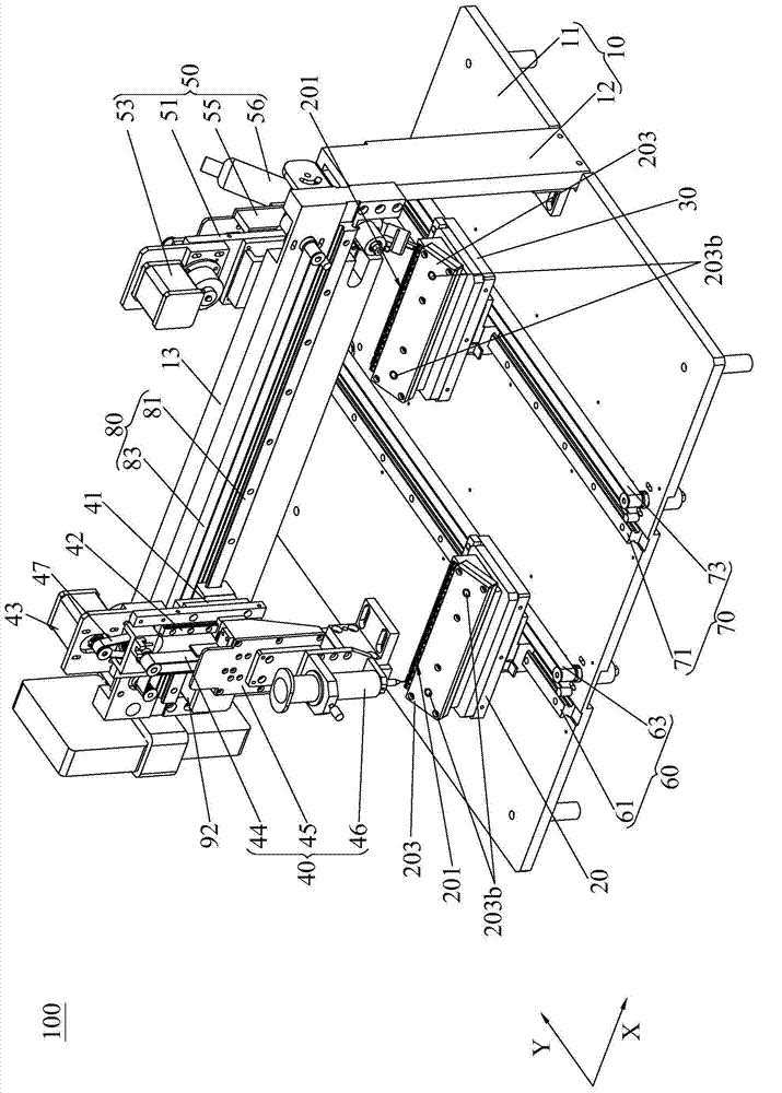
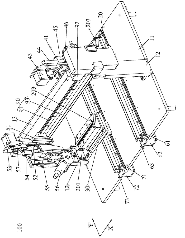
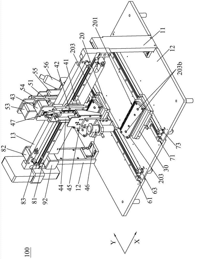
[0045] see Figure 1 to Figure 3 The welding machine 100 of the first embodiment of the present invention includes a frame 10, a first carrier 20, a solder feeding device 40, a solder curing device 50, and a first transfer device 60 and a material transfer device 80 that are all arranged on the frame 10. And curing transfer device 90, the first carrier 20 is used to load the product 201 to be welded, wherein, the welding process of product 201 can be between the contact terminal (not marked in the figure) and the connector (not marked in the figure) Welding processing, but not limited thereto, will not be repeated here. The frame 10 has a soldering station and a curing station distributed along a Y axis, the first carrier 20 is arranged on the first transfer dev...


PUM


Abstract

The invention discloses a welding machine. The welding machine comprises a rack, a first carrier, a welding flux feeding device, a welding flux solidifying device, a first transporting device, a feeding transporting device and a solidifying transporting device, wherein the first transporting device, the feeding transporting device and the solidifying transporting device are arranged on the rack. The rack is provided with a welding flux containing station, a solidifying station and a first processing route, wherein the welding flux containing station and the solidifying station are distributed along the Y axis, and the first processing route is distributed along the X axis which staggers the Y axis. The first transporting device drives the first carrier to carry out reciprocating movement between the welding flux containing station and the solidifying station along the Y axis. The welding flux feeding device is opposite to the welding flux containing station. The feeding transporting device can drive the welding flux feeding device to carry out reciprocating movement in the first processing route, so that welding flux feeding is carried out on a product loaded by the first carrier which moves to the welding flux containing station by the welding flux feeding device. The welding flux solidifying device is opposite to the solidifying station. The solidifying transporting device can drive the welding flux solidifying device to carry out reciprocating movement in the first processing route, so that heating and solidifying are carried out on the product loaded by the first carrier which moves to the solidifying station by the welding flux solidifying device.

Description

technical field [0001] The invention relates to the field of welding processing, in particular to a welding machine and a welding processing method thereof. Background technique [0002] As we all know, wires have been widely used to connect electronic devices such as notebook computers, digital cameras, and mobile phones. When connecting electronic devices with wires, it is often necessary to provide connectors at the ends of the wires, and the connectors need to be welded with contact terminals. In the prior art, the product welding process of welding the contact terminal to the connector is carried out manually, that is, manually operating an electric soldering iron to heat and solidify solder such as solder paste or solder to connect the contact terminal The terminal is welded to the connector to complete the welding process of the product. [0003] On the one hand, the welding tools used in the manual welding method are extremely simple, and it is necessary to use mult...

Claims


Application Information

Patent Timeline
Patent Type & Authority Applications(China)
IPC IPC(8): B23K3/00B23K3/04B23K3/06B23K3/08B23K1/002B23K1/005
CPCB23K1/002B23K1/005B23K3/00B23K3/04B23K3/06B23K3/08
Inventor 姚天金
Owner DONGGUAN SANXIN PRECISION MACHINERY
Why Eureka
Try Eureka