
Fixture for welding patch component to heat dissipation metal strip

A technology of patch devices and metal strips, applied in the field of special fixtures, can solve the problems of uneven surface quality, uneven solder joints, product damage, etc., to ensure the welding quality, improve work efficiency, and reduce the effect of damage rate

Active Publication Date: 2015-06-24
TIANJIN 712 COMM & BROADCASTING CO LTD
View PDF6 Cites 5 Cited by
  • Summary
  • Abstract
  • Description
  • Claims
  • Application Information

AI Technical Summary

Problems solved by technology

During the welding process, due to the manual operation method, limited by the level and tools of each operator, several operations must be performed on a heat dissipation metal strip, so the SMD device has to withstand several times for a long time at 300° The above high temperature test, and uneven solder joints after completion, the finished product is often found to be damaged during the debugging process, and the surface quality is also uneven
Cause damage to the device and waste of working hours, the loss is huge

Method used


Image

  • Fixture for welding patch component to heat dissipation metal strip
  • Fixture for welding patch component to heat dissipation metal strip
  • Fixture for welding patch component to heat dissipation metal strip

Examples


Embodiment Construction

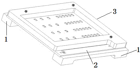
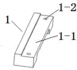
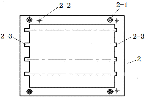
[0017] like Figures 1 to 7 As shown, a jig for soldering a chip device and a heat dissipation metal strip includes a bracket 1 , a positioning frame 2 , and a solder paste printing jig 3 .

[0018] The bracket 1 is a strip, and two screw holes 1-2 are arranged in the concave surface 1-1 of the bracket 1 .

[0019] The positioning frame 2 is a rectangular frame structure, and four counterbores 2-1 and three positioning holes 12-1 are arranged on the upper and lower frame surfaces of the positioning frame 2. Four positioning slots 2-3.

[0020] The solder paste printing fixture 3 includes a handle-shaped frame 3-1 and a solder paste printing surface 3-2, and three alignment pin holes II3-1-1 are provided on the handle-shaped frame 3-1 surface, and three positioning pin holes II3-1-1 are arranged on the solder paste printing surface 3-1. 2 is provided with several solder paste leakage holes 3-2-1, and the solder paste printing surface 3-2 is bonded on the handle-shaped frame 3...


PUM


Abstract

The invention relates to a fixture for welding a patch component to a heat dissipation metal strip. Two supports are arranged correspondingly, two end faces of a locating frame are fixed in concave surfaces of the two correspondingly arranged supports respectively, and a tin cream printing jig is located on the locating frame. The fixture for welding the patch component to the heat dissipation metal strip has the advantages that the biggest improvement compared with a former manual welding is that the component consistency of the product after welded is guaranteed, the welding quality is guaranteed, the hidden danger of component damage due to multi-pass operations is avoided, and the damage degree of the component is reduced. The requirement for the welding level of operational personnel is not high, only does the component need to be placed in a corresponding position, the working efficiency is improved, and the operational personnel and production managers are pleased to use.

Description

technical field [0001] The invention relates to a special fixture, in particular to a fixture for welding a patch device and a heat dissipation metal strip, which is mainly used for welding a patch component and a metal heat dissipation metal strip, and can be extended to a patch device and a metal Soldering of high heat dissipation materials. Background technique [0002] In the production process of our factory, because the heat dissipation metal strip is different from the printed board, the shape and size are very different, and there is no pad mark, so it cannot be directly placed on the placement machine for placement. Due to the above reasons, both Soldered by hand. In the manual soldering process, since the material of the metal heat sink is copper, the heat dissipation performance is good, and the temperature cannot be effectively transmitted to the soldering surface of the device during soldering. Therefore, the traditional soldering operation method requires two ...

Claims


Application Information

Patent Timeline
Patent Type & Authority Applications(China)
IPC IPC(8): B23K3/08B23K37/04
CPCB23K3/087
Inventor 霍晓莉刘素欣刘景晔
Owner TIANJIN 712 COMM & BROADCASTING CO LTD
Learn More