
Frication stir welding molding device and welding method thereof

A technology of friction stir welding and stirring head, which is applied in the direction of welding equipment, non-electric welding equipment, metal processing equipment, etc. It can solve the problems of stop working, difficult welding of the bottom layer, high surface temperature, etc., and achieve the effect of facilitating flow and uniformity

Inactive Publication Date: 2015-06-24
SHANDONG UNIV OF SCI & TECH
View PDF6 Cites 4 Cited by
  • Summary
  • Abstract
  • Description
  • Claims
  • Application Information

AI Technical Summary

Problems solved by technology

Friction stir welding has its unique advantages in sheet metal welding. However, due to the synchronous rotation of the stirring head and the stirring shoulder in the existing technology, the upper surface of the weldment not only generates heat by friction with the stirring head, but also generates heat by friction with the stirring shoulder. The upper and lower "funnel" temperature field, the surface temperature is high, the deep layer temperature is low, and the bottom layer of the welding zone has not yet reached the plastic state required for welding, making it difficult to weld the bottom layer, or at the expense of overheating the upper layer structure, to improve the lower plate. temperature, and some alloy plates have strict restrictions on welding temperature and time, this phenomenon is more prominent in thick plate welding, therefore, it is urgent to propose a method to solve the "funnel" temperature field existing in friction stir welding question
[0003] In addition, since the resonance frequency of the ultrasonic vibration device is sensitive to factors such as external loads and thermal loads, changes in these factors will cause changes in the resonance frequency of the ultrasonic vibration device, resulting in detuning or stoppage of the ultrasonic vibration device.

Method used


Image

  • Frication stir welding molding device and welding method thereof
  • Frication stir welding molding device and welding method thereof

Examples


Embodiment 1

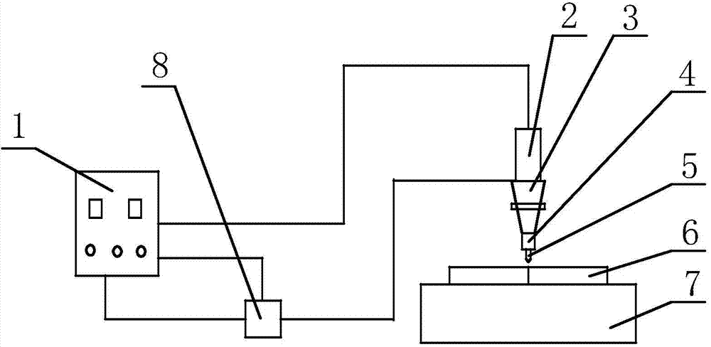
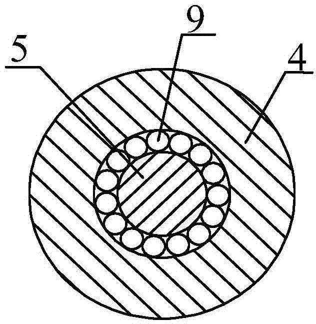
[0023] Such as figure 1 As shown, a friction stir welding forming device includes a motor, a stirring shoulder 4, a stirring head 5, and an ultrasonic device. There are two motors. The stirring shoulder 4 is connected to the shaft of the motor through a bearing. The head 5 is sheathed with gears, and the motor shaft is also sheathed with gears. The two gears mesh to transmit the power of the motor to the mixing head 5. The ultrasonic device includes an ultrasonic generator 1, a transducer 2, and a horn 3 connected in sequence, and also includes a frequency tracker 8. Both ends of the frequency tracker 8 are connected to the ultrasonic generator 1 and the ultrasonic generator 1 and the The transducer 2 is connected by a wire, and the horn 3 is welded to the stirring shoulder 4. The frequency tracker 8 collects the frequencies of the ultrasonic generator 1 and the transducer 2 respectively, and controls the ultrasonic generator 1 through the frequency tracking signal so that the ...


PUM


Abstract

The invention discloses a frication stir welding molding device and a welding method thereof. The frication stir welding molding device comprises two motors, a stirring shoulder, a stirring head and an ultrasound device. The ultrasound device comprises an ultrasonic generator, a transducer and an amplitude-change pole which are connected in sequence. A through hole is formed in the center of the stirring shoulder, the diameter of the through hole is larger than that of the stirring head, the stirring head penetrates through the through hole, the stirring head and the stirring shoulder are movably connected with the motors, and the amplitude-change pole is fixedly connected with the stirring shoulder. The ultrasound device further comprises a frequency tracker, and the two ends of the frequency tracker are connected with the ultrasonic generator and the transducer respectively. When welding is conducted, the rotation direction of the stirring shoulder is opposite to that of the stirring head, and the rotation speed of the stirring head is 1.5-3 times that of the stirring shoulder. According to the device and the method, occurrence of a hopper type temperature field is avoided in the welding process, and uniformity of welded joint structures is guaranteed.

Description

Technical field [0001] The invention relates to the technical field of metal welding, in particular to a friction stir welding forming device and a welding method thereof. Background technique [0002] Friction welding is a method that uses the heat generated by the mutual movement and friction of the end faces of the plates to make the ends reach a thermoplastic state, and then quickly upset to complete the welding. Friction stir welding has its unique advantages in welding of plates. However, because the existing technology uses the stirring head and the stirring shoulder to rotate simultaneously, the upper surface of the welding piece not only friction and heat with the stirring head, but also friction and heat with the stirring shoulder, forming in the welding zone The “funnel-type” temperature field with high top and low bottom, high surface temperature, low deep layer temperature, the bottom layer of the welding zone has not yet reached the plastic state required for weldin...

Claims


Application Information

Patent Timeline
IPC IPC(8): B23K20/12B23K20/24
CPCB23K20/122B23K20/1245
Inventor 苏春建赵俊敏王清张鹏李宁王薛涛张景安叶帅
Owner SHANDONG UNIV OF SCI & TECH
Learn More