
Inverter grounding system

A technology of grounding system and inverter, which is applied in the direction of AC network circuit, power transmission AC network, emergency protection circuit device for limiting overcurrent/overvoltage, etc., which can solve the problem of increasing project cost, manufacturing cost and large volume, Elevation and other issues, to achieve the effect of strong adaptability

Active Publication Date: 2015-06-24
STATE GRID CORP OF CHINA +1
View PDF6 Cites 6 Cited by
  • Summary
  • Abstract
  • Description
  • Claims
  • Application Information

AI Technical Summary

Problems solved by technology

The advantage of this scheme is that the reactor shares the fault current, the pressure on the connected transformer is small, and the reactor can also play a role in limiting the short-circuit current. The disadvantage is that for high voltage levels, the reactive power absorbed by the shunt reactor itself Larger, may have a greater impact on the system, and the manufacturing cost and volume will also be larger
In addition, due to the inherent defect that the existing technology cannot effectively deal with the DC fault of the MMC converter, if the DC side of the MMC converter is grounded, the probability of bipolar short-circuit faults occurring on the DC side will increase
[0017] For power systems with a voltage level of 110kV and above, if the neutral point ungrounded system is adopted, the voltage of the non-faulty phase will rise to the line voltage, and the insulation level of the power transmission and transformation equipment needs to be considered according to the line voltage of the power grid, thereby increasing project cost

Method used


Image

  • Inverter grounding system
  • Inverter grounding system
  • Inverter grounding system

Examples


Embodiment 1

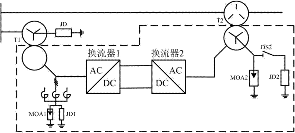
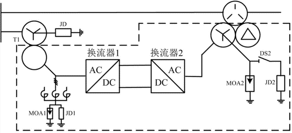
[0049] The invention of this example provides a converter grounding system. The system is aimed at the characteristics of the MMC converter with a half-bridge structure and the requirement that the valve side winding of the parallel transformer cannot adopt a star-shaped grounding method. Taking the unified power flow controller as an example, This application proposes a grounding method applicable to the unified power flow controller, convertible static compensator and unified power quality regulator, as shown in the attached figure 1 shown in . Wherein, the DC side of the converter 1 is connected to the DC side of the converter 2 . Inverter 1 / Inverter 2 may be an MMC converter, an H-bridge cascaded converter, a flying capacitor converter, or a diode-clamped converter. The AC side of the converter 1 is connected in parallel with the system through a parallel transformer T1. The parallel transformer T1 has only two windings, and the winding on the system side of the parallel...


PUM


Abstract

The invention relates to an inverter grounding system. Inverters are inverters of the MMC, or inverters of H-bridge cascade connection, or inverters of a flying capacitor or inverters of a diode clamper. The system comprises the inverters with the direct current sides being connected. The alternating-current side of one of the inverters is connected with a power system through a transformer in parallel. The alternating-current side of the inverter is connected with a star-connection electric reactor in parallel. The alternating side of the other inverter is connected with the system in series through connection with another transformer. According to the technical scheme, according to the characteristic of an MMC technology, a unified power flow controller is fully considered, and to solve the special problem that a star-shaped grounding mode cannot be adopted for a convertible static compensator, a unified power quality conditioner and other parallel connection transformer valve side windings, an inverter grounding mode suitable for the unified power flow controller, the convertible static compensator and the unified power quality adjuster are researched and proposed.

Description

Technical field: [0001] The invention relates to the field of power electronic devices, and more specifically relates to a grounding system for a converter. Background technique: [0002] The neutral point of the power system refers to the neutral point of the star-connected transformer (or generator). The neutral point grounding mode of the power system is divided into two types: the neutral point effective grounding mode and the neutral point non-effective grounding mode. Neutral point non-effective grounding methods can be divided into neutral point non-grounding method, neutral point low resistance grounding method, neutral point high resistance grounding method and neutral point resonance grounding method. [0003] The neutral point high-resistance grounding method means that at least one wire or point in the system is grounded through high resistance, the equivalent zero-sequence resistance of the system is not greater than the distributed capacitive reactance of the ...

Claims


Application Information

Patent Timeline
IPC IPC(8): H02H9/04H02J3/00H02J3/36H02J3/18
CPCY02E40/30Y02E60/60
Inventor 戴朝波宋洁莹
Owner STATE GRID CORP OF CHINA
Learn More