Motor stator iron core, motor stator, motor, and manufacturing method of motor stator
A motor stator and iron core technology, which is applied in the manufacture of stator/rotor body, magnetic circuit shape/style/structure, magnetic circuit static parts, etc., can solve the problem of low flux density of stator core, low material utilization rate and motor performance Improve the magnetic density, high material utilization, and reduce weight
- Summary
- Abstract
- Description
- Claims
- Application Information
AI Technical Summary
Problems solved by technology
Method used
Image
Examples
Embodiment 1
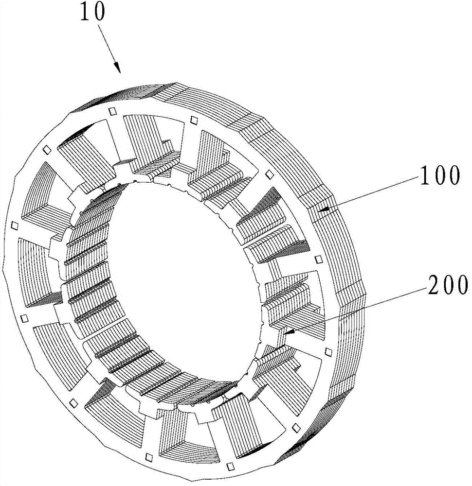
[0056] Such as figure 1 with figure 2 As shown, a motor stator core 10 provided by the embodiment of the present invention includes a core body part 100 and a tooth shoe boss part 200 assembled at one or both ends of the iron core body part 100. The tooth shoe boss part 200 In contact with the end of the iron core body 100 and protruding from the end of the iron core body 100, the tooth shoe boss portion 200 and the iron core body 100 can be separately prepared and connected by assembling, or The iron core body 100 is prepared first, and then the tooth shoe bosses 200 are assembled at one or both ends of the iron core body 100. The split structure can be adopted, and powder metallurgy and other methods are not required for molding, and the production cost is low. By adding the boss portion 200 of the tooth shoe, the purpose of increasing the axial length of the motor stator core 10 can be achieved without increasing the length of the winding turns; moreover, the boss portion...
Embodiment 2
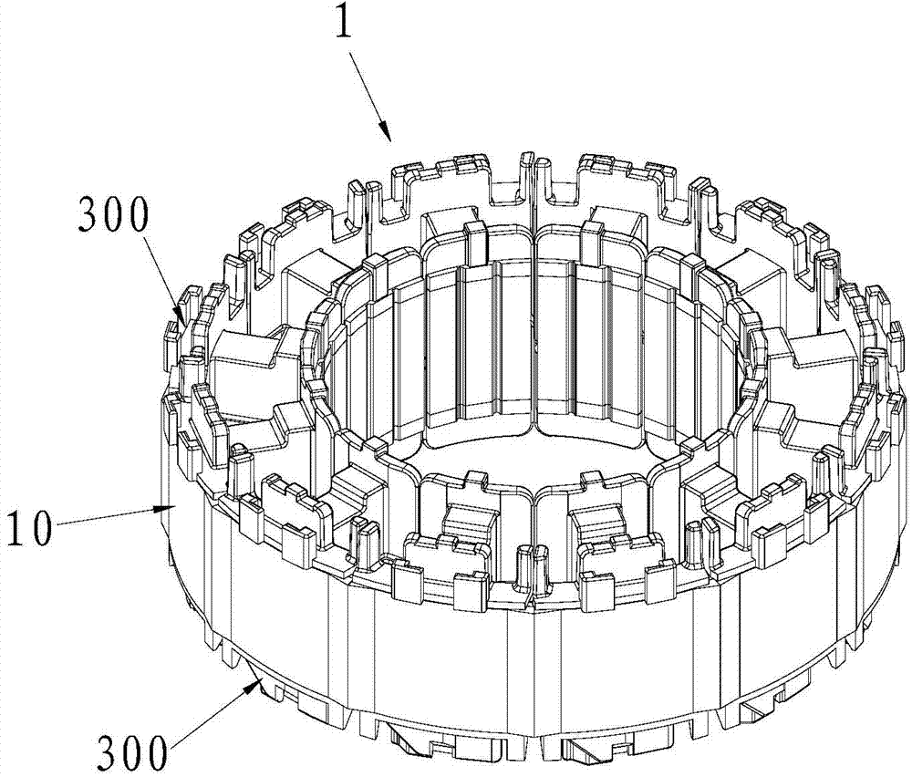
[0060] Such as Figure 3 to Figure 14 As shown, the embodiment of the present invention also provides a motor stator, including a motor stator core 10 and a winding (not shown in the figure) wound around the motor stator core 10 . The motor stator core 10 includes a core body part 100 and a tooth shoe boss part 200 assembled at one or both ends of the iron core body part 100. In a specific application, the tooth shoe boss part 200 can be arranged at one end of the iron core body part 100 , can also be separately provided at both ends of the iron core body part 100 . The tooth shoe boss 200 is in contact with the end of the core body 100 and protrudes from the end of the iron core body 100. The tooth shoe boss 200 can guide the magnetic flux of the magnet on the rotor to the stator teeth. On the other hand, the magnetic concentration effect is better, the magnetic density of the stator core can be improved, the material utilization rate is higher, the weight of the stator core...
Embodiment 3
[0077] An embodiment of the present invention provides a motor, which may be a permanent magnet brushless motor. The above motor includes a rotor and the motor stator in the second embodiment. The motor stator core 10 of the motor stator can adopt a conventional lamination structure, which can be mainly composed of two parts: one part is a conventional structure with teeth and yokes, and the other part is the tooth shoe boss part 200, which can be passed through The connecting piece 300 is connected, and the connecting piece 300 can be provided with a boss with a boss receiving groove 301 , and the boss can be used to place the boss portion 200 of the tooth shoe. By adding the tooth shoe boss portion 200, the axial length of the motor stator core 10 can be increased without increasing the winding turn length. Moreover, powder metallurgy materials are not used, and the punching structure is adopted, and the material cost is lower; the tooth shoe boss part 200 can be punched ou...
PUM
 Abstract
Description
Claims
Application Information
 - R&D
- Intellectual Property
- Life Sciences
- Materials
- Tech Scout
- Unparalleled Data Quality
- Higher Quality Content
- 60% Fewer Hallucinations
Browse by: Latest US Patents, China's latest patents, Technical Efficacy Thesaurus, Application Domain, Technology Topic, Popular Technical Reports.
© 2025 PatSnap. All rights reserved.Legal|Privacy policy|Modern Slavery Act Transparency Statement|Sitemap|About US| Contact US: help@patsnap.com


