Blast furnace slag water quenching steam waste heat recovery device

A technology of steam waste heat and recovery device, applied in furnaces, waste heat treatment, furnace components, etc., can solve the difficulty of steam waste heat recovery, the thermal conductivity and air permeability affect the heat exchange between slag and cold air and water wall, and the loss of flushing. Problems such as residual heat of slag water

Active Publication Date: 2015-07-01
HIT HARBIN INST OF TECH KINT TECH
View PDF2 Cites 5 Cited by
  • Summary
  • Abstract
  • Description
  • Claims
  • Application Information

AI Technical Summary

Problems solved by technology

[0008] The second is the recovery of sensible heat from blast furnace slag. The successful industrial application of this method has not yet been reported.
This process of first solidification and then granulation has great disadvantages: the thermal conductivity and air permeability of the flat high-temperature slag seriously affect the heat exchange between the slag and the cold air and water wall
[0014] In the 1950s, my country conducted some research on waste heat recovery and dry granulation of blast furnace slag, but they were not successful, and no in-depth research was carried out since then.
[0015] The third is to use slag flushing steam to generate electricity, this method is limited to the feasibility study
This not only wastes water resources, but also loses valuable residual heat of flushing slag water.
[0022] As mentioned above, 10% of the waste heat of blast furnace slag is in the slag washing water, and 80-90% of the waste heat of blast furnace slag runs away with the evaporated steam, because a lot of air is mixed in the steam generated during the water quenching of blast furnace slag, so this It is very difficult to recover the waste heat of part of the steam, and there is no complete success case so far

Method used


Image

  • Blast furnace slag water quenching steam waste heat recovery device
  • Blast furnace slag water quenching steam waste heat recovery device
  • Blast furnace slag water quenching steam waste heat recovery device

Examples


Embodiment Construction

[0031] The present invention will be described in further detail below in conjunction with the accompanying drawings and embodiments.

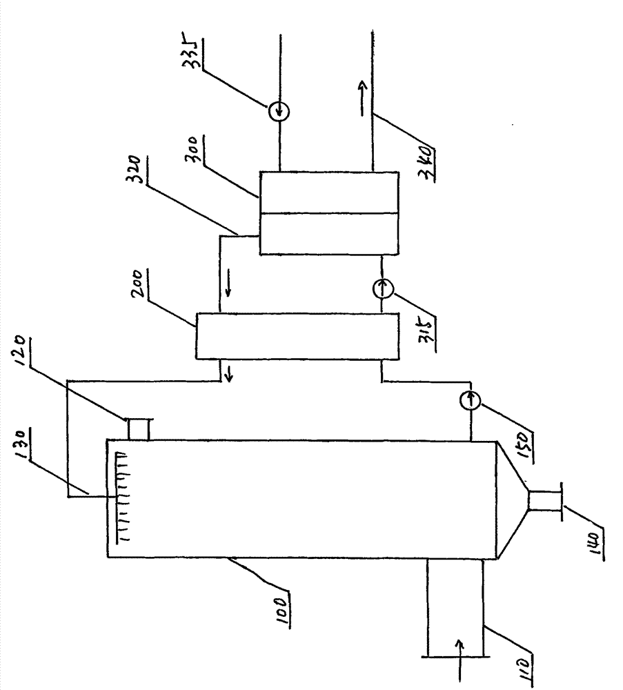
[0032] figure 1 The overall diagram of the embodiment of the blast furnace slag water quenching steam waste heat recovery device of the present invention is given.

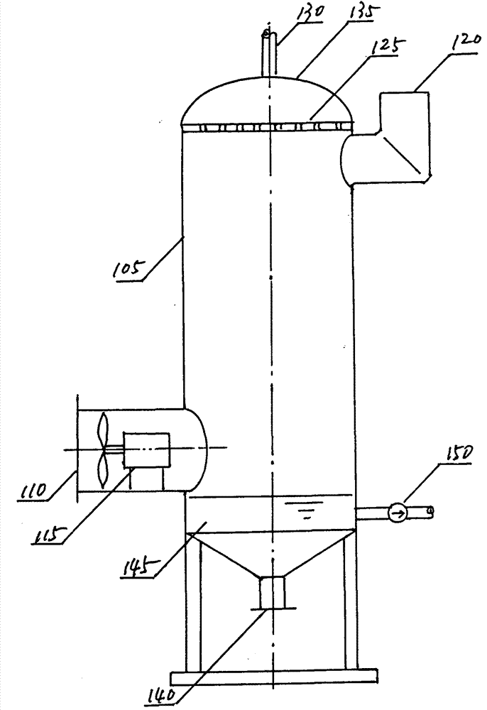
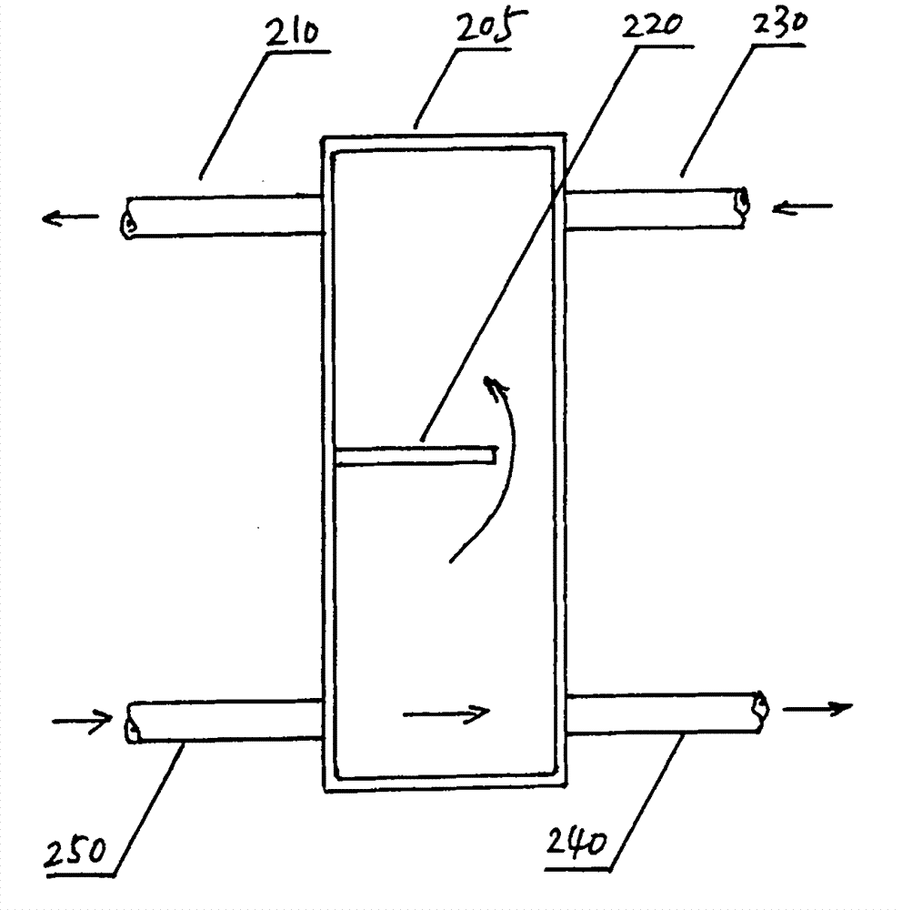
[0033]The embodiment of the blast furnace slag water quenching steam waste heat recovery device of the present invention is generally composed of three parts: a spray heat exchanger 100 , a hybrid heat exchanger 200 and a flow channel heat exchanger 300 . The waste heat of blast furnace slag water quenching steam passes through three-stage heat exchange, and transfers the heat to the heating circulating water to supply heat to users.

[0034] First, the water vapor generated by water quenching of blast furnace slag enters the spray heat exchanger from the steam inlet 110 at the lower part of the spray heat exchanger 100, and the spray water enters the spray water from the spray w...


PUM


Abstract

The invention provides a blast furnace slag water quenching steam waste heat recovery device. The device is composed of a spray-type heat exchanger and a runner type heat exchanger; in the spray-type heat exchanger, the water steam generated by blast furnace slag water quenching comes into contact with spraying water to exchange heat; in the runner type heat exchanger, heating circulating water exchanges heat with intermediary water, and then supplies heat to users by use of pipelines. The blast furnace slag water quenching steam waste heat recovery device is characterized by further comprising a mixed heat exchanger. Only one water baffle plate is arranged inside the mixed heat exchanger, and the other part inside the mixed heat exchanger is a cavity; the entering spraying water and the intermediary water are mixed together in addition to heat exchange; the water baffle plate functions in improving the flowing resistance, so that water flowing out of an intermediary water outlet can be completely the spraying water entering from a spraying water inlet and at a relatively high temperature; besides, the left spraying water at the relatively high temperature flows through the water baffle plate and flows out of a spraying water outlet together with the intermediary water entering via an intermediary water inlet.

Description

technical field [0001] The invention relates to thermal technology, in particular to a waste heat recovery device for blast furnace slag water-quenched steam. Background technique [0002] my country is already a big country in steel production, and the annual output of steel accounts for 40% of the world's total output. Whether it is steelmaking or ironmaking, a large amount of slag will be produced. Slag is produced along with iron and steel. It is a by-product of iron and steel smelting, and it is also the basic condition for a series of important metallurgical reactions. It directly participates in the physical and chemical reactions and mass and heat transfer processes of iron and steel smelting. It not only affects the output of iron and steel, quality, and is closely related to the consumption of raw materials and energy. [0003] In iron and steel metallurgical furnaces, high-temperature slag at 1400-1500°C is produced. After flowing out through the slag mouth, and...

Claims


Application Information

Patent Timeline
Patent Type & Authority Applications(China)
IPC IPC(8): C21B3/08F27D17/00
CPCC21B3/08C21B2200/00F27D17/004Y02P10/25
Inventor 李伟李金峰尚德敏
Owner HIT HARBIN INST OF TECH KINT TECH
Why Eureka
Try Eureka