Solid garbage intercepting and concentrating device for river

A technology for solid waste and rivers, which is applied in water conservancy projects, sea area projects, and cleaning of open water surfaces. It can solve problems such as hidden safety hazards on the surrounding river banks, river obstruction, and poor practicability. Sophisticated Effects

Inactive Publication Date: 2015-07-01
WUXI HAOYU ENERGY SAVING ENVIRONMENTAL PROTECTION EQUIP CO LTD
View PDF9 Cites 4 Cited by
  • Summary
  • Abstract
  • Description
  • Claims
  • Application Information

AI Technical Summary

Problems solved by technology

[0003] For example, the patent No. 201020156992.4 is a self-flowing sewage intercepting device for rivers, which belongs to the sewage removal device for rivers. It consists of a front top plate and a rear top plate respectively installed above the middle support and the left and right frames, a front bottom plate and a rear bottom plate respectively installed at the bottom, a front block is installed vertically between the front top plate and the front bottom plate, and a front block is installed vertically between the rear top plate and the rear bottom plate. Install the rear baffle vertically between the two sides, install the river bottom support fixed on the bottom of the river under the rear bottom plate, install the filter screen on the bottom steps of the filter tank between the middle supports above the front bottom plate and the rear bottom plate, and the left and right frames. The filter layer is installed on the top of the filter screen, and the utility model is installed in the water flow direction along the lower edge of the dam crest. The river intercepts the sewage by itself, removes the dirt in the river water, and makes the water quality of the river clean. It is convenient and timely to deal with. After long-term accumulation, it will seriously hinder the river and affect the flow of downstream rivers. It is also easy to overflow the river during the flood season, which will bring safety hazards to the surrounding river banks, and the practicability is poor.
[0004] Also, the patent number is 201410232477.2, a small-flow river water purification and pollution interception system, including: bank-based ecological bed, leisure hydrophilic gallery, ecological filter bed, water diversion rubber dam; the bank-based ecological bed is located on both sides of the river, for Slope-type structure, the shore-based ecological bed is separated from the water body by a leisure hydrophilic gallery, a filter layer is provided on the side where the bank-based ecological bed contacts the leisure hydrophilic gallery, and the leisure hydrophilic gallery The bottom of the platform is provided with several outlets; the ecological filter bed is located in the water body of the river, near the side of the river bank, the middle of the two ecological filter beds is the central area of ​​the river, and the central area between the ecological filter bed and the river is formed by a permeable retaining wall and a permeable The water-dividing rubber dam on the retaining wall is separated; the ecological filter bed is divided into upper and lower layers, the lower layer is the filter material layer, and the upper layer is the soil layer; the ecological filter bed is a rectangular or arc-shaped structure, opening toward the upstream of the river to receive For the river water from the upper reaches, this solution only uses ecological soil filtration technology to purify the river water. Although the water purification is thorough enough, it is prone to soil erosion, and the filtration speed is slow, which cannot meet other requirements for water purification.

Method used


Image

  • Solid garbage intercepting and concentrating device for river
  • Solid garbage intercepting and concentrating device for river
  • Solid garbage intercepting and concentrating device for river

Examples


Embodiment Construction

[0032] The preferred technical solutions of the present invention will be described in detail below in conjunction with the accompanying drawings.

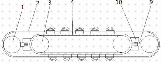
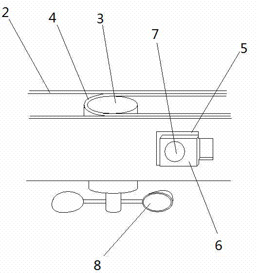
[0033] As shown in the figure, a device for intercepting and concentrating solid waste in a river includes columns 1 respectively arranged on both sides of the river, and synchronously rotating components are arranged on the columns 1, and the columns 1 can be installed at the bottom of the river or fixed on the embankment to rotate synchronously The assembly also includes an outer winding belt 2 that is arranged around the two uprights 1, and a rotating shaft 3 is respectively arranged in the outer winding 2 close to the two uprights 1, and an inner winding 4 is arranged around the two rotating shafts 3, and the inner The circumference of the belt 4 is smaller than the circumference of the outer belt 2, and the outer belt 2 is provided with equidistant perforations 5 in the direction of rotation, and the rotation direction of the ...


PUM


Abstract

The invention discloses a solid garbage intercepting and concentrating device for a river. The solid garbage intercepting and concentrating device comprises stand columns arranged on both sides of the river respectively. The stand columns are provided with a synchronous rotating assembly. The synchronous rotating assembly comprises an external winding belt rotating around the two stand columns. An internal winding belt is arranged in the external winding belt. The external winding belt is provided with penetrating holes in the rotating direction. The internal winding belt is provided with penetrating components corresponding to the penetrating holes. The penetrating components are provided with intercepting components for bonding garbage. Garbage cleaning components are arranged, and a river surface flow diversion layer is arranged between the stand columns. Compared with the prior art, according to the solid garbage intercepting and concentrating device for the river, the internal winding belt is inserted into the penetrating holes through the penetrating components to drive the external winding belt to rotate synchronously, the garbage bonded by the intercepting components is cleared and processed in a concentrated mode, the river surface flow diversion layer intercepts the garbage floating on the river surface, a certain clearing function is played on various garbage in the river, and the water quality is purified.

Description

technical field [0001] The invention relates to a river water quality cleaning device, in particular to a device for intercepting and concentrating solid waste in a river. Background technique [0002] In the rivers near some populated areas, the occurrence rate of daily garbage is significantly higher than that of rivers in other areas. With the accumulation of pollutants in the river water, the pollution degree of the river continues to increase, and the water environment is deteriorating day by day. The quality is also gradually declining, and daily garbage is mostly solid waste, such as plastic products, paper products, etc., which are difficult to decompose in water, and usually flow downstream with the river, which has a great impact on the downstream water quality. [0003] For example, the patent No. 201020156992.4 is a self-flowing sewage intercepting device for rivers, which belongs to the sewage removal device for rivers. It consists of a front top plate a...

Claims


Application Information

Patent Timeline
Patent Type & Authority Applications(China)
IPC IPC(8): E02B15/06E02B3/00
Inventor 胡晓荣俞娟胡瑜
Owner WUXI HAOYU ENERGY SAVING ENVIRONMENTAL PROTECTION EQUIP CO LTD
Why Eureka
Try Eureka