
A heat recovery low energy consumption defogging swimming pool

A technology of heat recovery and low energy consumption, applied in the field of swimming facilities, can solve the problems of increasing the overall energy loss, non-compliance, and environmental pollution of swimming pools, and achieve the effects of improving indoor visibility, realizing automatic temperature, and protecting the environment

Active Publication Date: 2016-11-23
天津奥纳富霖科技有限公司
View PDF9 Cites 0 Cited by
  • Summary
  • Abstract
  • Description
  • Claims
  • Application Information

AI Technical Summary

Problems solved by technology

[0002] Swimming is recognized as the best fitness exercise, but swimming is often affected by seasons. If the swimming pool is operated in winter, it will often consume a lot of energy such as electricity, natural gas or coal to heat water and maintain a constant temperature, resulting in a large amount of carbon dioxide. and various harmful substances, not only consumes energy but also pollutes the environment, making swimming in winter very expensive and difficult to promote
At the same time, part of the waste water with waste heat is directly discharged, which also virtually increases the overall energy loss of the swimming pool
[0003] The Chinese utility model patent "A Solar Energy-Assisted Ground Biogas Device" (CN 203976806) discloses a device that utilizes solar heat collectors, air source heat pump hot water units, etc. to provide thermal energy for biogas fermentation. The method of transferring solar energy and air heat energy is used to heat the biogas digester, but the excess energy cannot be effectively stored. That is, when there is no solar energy and air heat energy can be used when the temperature difference is large, the power consumption of its work will be very large, which is not in line with the current energy saving. Environmental needs

Method used


Image

  • A heat recovery low energy consumption defogging swimming pool

Examples


Embodiment Construction

[0022] Embodiments of the present invention will be further described below in conjunction with the accompanying drawings.

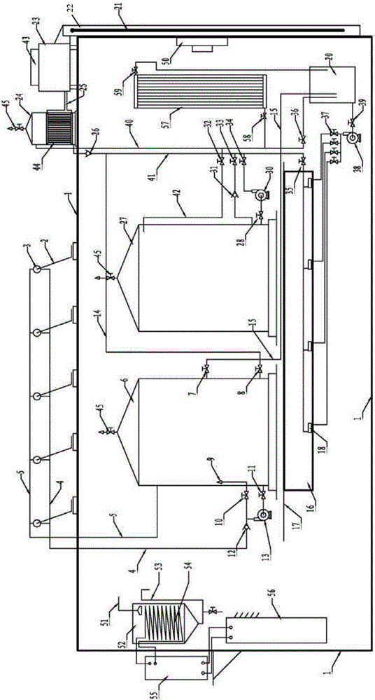
[0023] Such as figure 1 As shown, a heat recovery low-energy defogging swimming pool generally includes four parts, and its composition and working method are as follows:

[0024] (1) Solar absorption energy storage unit

[0025] Including multiple sets of solar absorbing units composed of solar vacuum tubes 2 and solar water storage tanks 3 arranged outside the wall 1, through solar water inlet pipes 4, solar water outlet pipes 5, water pumps A 13, valves D 11, one-way valves A 12 and The solar water storage tank 6 arranged inside the wall constitutes a water circulation solar energy absorption and energy storage system.

[0026] Solar water storage tank 6 keeps full during work, start water pump A 13 when the sun shines strongly, solar water storage tank 6 stores water through valve D11, water pump A 13, one-way valve A 12, solar water inlet pipeline...


PUM


Abstract

The invention discloses a heat-recovery low-energy-consumption demisting natatorium which comprises a wall body, a solar absorption energy-storage unit, an air source heating energy-storage unit, a natatorium pipeline heat supply unit, a ventilating and air heat recovering unit, a demisting and waste water heat recovering unit and a demisting and heat supply unit. A valve and a water pump are controlled through a control module to switch heating modes of the natatorium pipeline heat supply unit. The ventilating and air heat recovering unit, the demisting and waste water heat recovering unit and the demisting and heat supply unit can recover waste heat of waste water and waste air while improving indoor visibility and purifying air, energy consumption is further reduced, and environment is protected. Solar energy and air heat energy are reasonably utilized to enable swimming pools to be at constant temperature and be controllable and enable pool water to be dynamically circulated, and a waste water and waste air heat recovery system is added for the natatorium, so that the utilization rate of the swimming pools is improved while energy saving and environment protection are achieved, and the low-cost heat supply requirement of the swimming pools in winter is met.

Description

technical field [0001] The invention relates to swimming facilities, more specifically, to a heat recovery and low energy consumption defogging swimming pool. Background technique [0002] Swimming is recognized as the best fitness exercise, but swimming is often affected by seasons. If the swimming pool is operated in winter, it will often consume a lot of energy such as electricity, natural gas or coal to heat water and maintain a constant temperature, resulting in a large amount of carbon dioxide. And various harmful substances, not only consume energy but also pollute the environment, make the cost of swimming in winter very high and be difficult to promote. At the same time, part of the waste water with waste heat is directly discharged, which also virtually increases the overall energy loss of the swimming pool. [0003] The Chinese utility model patent "A Solar Energy-Assisted Ground Biogas Device" (CN 203976806) discloses a device that utilizes solar heat collectors...

Claims


Application Information

Patent Timeline
Patent Type & Authority Patents(China)
IPC IPC(8): E04H3/16E04D13/18F24D15/00
CPCY02B10/20
Inventor 杨正华银永忠
Owner 天津奥纳富霖科技有限公司
Learn More