Diamond impregnated segment with tooth cavities

A technology of diamond and impregnated inserts, which is applied to cutting elements for geological drilling bits and oil fields, can solve the problem of not being able to prevent heart digging very well.

Inactive Publication Date: 2015-07-01
CHINA PETROCHEMICAL CORP +1
View PDF5 Cites 3 Cited by
  • Summary
  • Abstract
  • Description
  • Claims
  • Application Information

AI Technical Summary

Problems solved by technology

[0003] The present invention provides a diamond impregnated block with tooth pockets to solve the problem that the existi...

Method used


Image

  • Diamond impregnated segment with tooth cavities
  • Diamond impregnated segment with tooth cavities
  • Diamond impregnated segment with tooth cavities

Examples


Embodiment approach 1

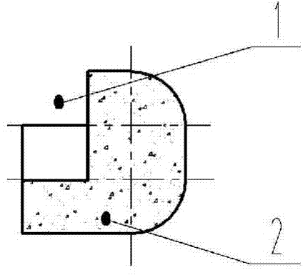
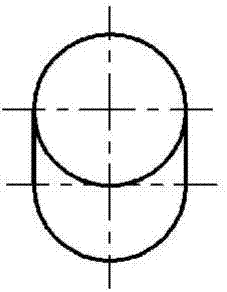
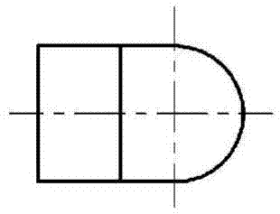
[0028] Such as Figure 1.1 , Figure 1.2 , Figure 1.3 The diamond impregnated block with tooth cavity shown is composed of tooth cavity 1 and diamond impregnated block 2. Tooth cavity 1 is the position for inserting cutting elements. The specific shape is determined by the shape of the cutting teeth used. Diamond impregnated block 2 is a mixed sintered body of diamond particles and matrix powder. The diamond particles are natural diamond particles, artificial diamond, thermally stable polycrystalline diamond and cubic boron nitride block. The matrix powder is 20%~70% tungsten carbide Powder, 20%~60% copper powder, 3%~20% nickel powder, 10%~60% cobalt powder. The arc surface and spherical surface on the diamond impregnated block 2 are to reduce stress concentration and enhance the welding strength of the impregnated block. The diameter of the tooth pocket 1 is the same as the width of the diamond impregnated block 2 .

Embodiment approach 2

[0029] Implementation mode two: if Figure 2.1 , Figure 2.2 , Figure 2.3 The diamond-impregnated insert with tooth holes shown is the same as that of Embodiment 1 Figure 1.1 , Figure 1.2 , Figure 1.3 The shown diamond impregnated insert with pockets differs in that the width of the diamond impregnated insert 2 is greater than the diameter of the pocket 1 . The curved surfaces of the diamond-impregnated inserts with tooth pockets also change accordingly.

Embodiment approach 3

[0030] Implementation mode three: if Figure 3.1 , Figure 3.2 , Figure 3.3 The diamond-impregnated insert with tooth holes shown is the same as that of Embodiment 1 Figure 1.1 , Figure 1.2 , Figure 1.3 The difference of the diamond impregnated block with tooth pockets shown is that two tooth pockets 1 are arranged on the diamond impregnated block 2, that is, the diamond impregnated block with double tooth pockets.

[0031] It is also possible to design a diamond impregnated block with more than three tooth cavities, the shape of the tooth cavity 1 changes with the shape of the cutting element, and the diamond impregnated block 2 can be designed into more shapes.

[0032] Such as Figure 4.1 , Figure 4.2 , Figure 4.3 As shown, a cutting element 3 is embedded in the tooth pocket 1 of the diamond-impregnated insert 2 with tooth pockets. In addition to the cylindrical shape, the cutting element 3 also has a fan-cylindrical, wedge-shaped, hexahedral, elliptical-cylind...


PUM


Abstract

The invention relates to a diamond impregnated segment with one to five tooth cavities, comprising one to five cutting elements and a segment body. The cutting elements are inserted into the tooth cavities arranged in one side of the segment body. The tooth cavities are as many as the cutting elements. The tooth cavities are in one or multiple of shapes, such as cylinder, sector column, wedge, hexahedron, elliptic cylinder and prism; the cutting elements matching with the tooth cavities are also in one or multiple of the shapes, such as cylinder, sector column, wedge, hexahedron, elliptic cylinder and prism. The diamond impregnated segment is applied to the center of a diamond impregnated bit, is low in linear speed and generates little heat; the cutting elements can run normally; the cutting elements coordinate with the diamond impregnated segment, allowing double safety, coring of the diamond impregnated bit is well prevented, and drilling footage can be increased. The diamond impregnated segment is suitable for petroleum and geological drill bits.

Description

technical field [0001] The invention belongs to cutting elements for oil and geological drilling bits. Background technique [0002] At present, impregnated diamond drill bits are widely used in petroleum and geological hard rock drilling, and have achieved good results. Existing diamond-impregnated inserts are mainly: 1. The cutter head or node used for stone saws, with a cuboid as the basic shape, and changing the two parallel faces of the cuboid into circular arc surfaces matching the diameter of the saw, in order to improve For sawing efficiency, the cutting edge is longitudinally layered or wavy, and in order to reduce sawing resistance, grooves are made on both sides of the cutter head. 2. The impregnated block used on the core bit is an approximate cuboid with two parallel surfaces matching the arc surface of the core bit. In order to improve the drilling efficiency, the top is designed with chamfering, layering, circumferential groove, sharp teeth, and spherical top...

Claims


Application Information

Patent Timeline
IPC IPC(8): E21B10/56
CPCE21B10/56
Inventor 彭烨李百钢樊胜华关舒伟王明瑞周保国燕东升贾炳军
Owner CHINA PETROCHEMICAL CORP
Why Eureka
Try Eureka