
A high-efficiency solar rapid drying equipment

A technology of fast drying and solar energy, applied in the field of solar drying, can solve the problems of low air thermal conductivity, prolonging the drying time of materials, uneven heating of materials, etc., and achieve the effect of changing the utilization mode, improving drying efficiency and reducing drying time

Active Publication Date: 2016-11-16
NORTHEASTERN UNIV LIAONING
View PDF4 Cites 1 Cited by
  • Summary
  • Abstract
  • Description
  • Claims
  • Application Information

AI Technical Summary

Problems solved by technology

[0005] When the above drying method is adopted, due to the low thermal conductivity of the air and the short contact time with the heat collector, the drying efficiency is not high and the drying time of the material is prolonged.
At the same time, the materials in most of the existing solar drying equipment are in a static state, which leads to uneven heating of the materials and unsatisfactory drying effect of the materials

Method used


Image

  • A high-efficiency solar rapid drying equipment
  • A high-efficiency solar rapid drying equipment
  • A high-efficiency solar rapid drying equipment

Examples


Embodiment Construction

[0020] The present invention will be further described in detail below in conjunction with the accompanying drawings and specific embodiments.

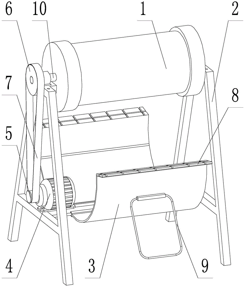
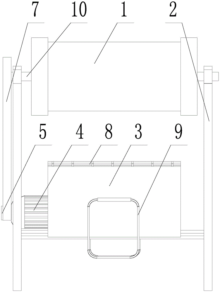
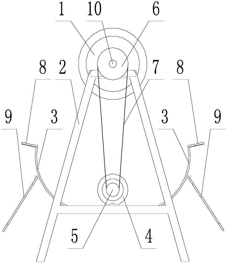
[0021] Such as figure 1 , 2 , 3, a high-efficiency solar energy fast drying equipment, including a drying cylinder 1, a bracket 2, a reflector 3, a driving motor 4, a driving pulley 5, a driven pulley 6 and a belt 7, and the drying cylinder 1 passes through a bearing Installed on the top of the support 2, the material inlet and outlet of the drying cylinder 1 is located on the same side of the cylinder; the drive motor 4 is arranged on the bottom of the support 2, and the driving pulley 5 is installed on the motor shaft of the drive motor 4, driven The pulley 6 is installed on the mandrel 10 of the drying cylinder 1, and the driving pulley 5 and the driven pulley 6 are connected by a belt 7; Corresponding to the reflective surface of the mirror 3.

[0022] A solar panel 8 is installed on the top edge of the reflector 3 , and the dr...


PUM


Abstract

A high-efficiency solar rapid drying equipment, including a drying cylinder, a bracket, a reflector, a driving motor, a driving pulley, a driven pulley and a belt. The drying cylinder is installed on the top of the bracket through a bearing, and the material inlet and outlet of the drying cylinder is located on the cylinder. on the same side; the driving motor is set at the bottom of the bracket, the driving pulley is installed on the motor shaft of the driving motor, the driven pulley is installed on the core shaft of the drying drum, and the driving pulley and the driven pulley are connected by a belt; The reflector is located obliquely below the drying cylinder, and the outer wall of the drying cylinder corresponds to the reflecting surface of the reflector; a solar panel is installed on the top edge of the reflector, and the drive motor is powered by the solar panel; the reflector and the bracket are hinged connected, and there are also legs hinged on the back of the reflector. The reflector adjusts the reflection angle through the legs; a spiral copying plate is installed on the inner wall of the drying cylinder; the outer wall of the drying cylinder is covered with a heat-absorbing layer; the reflecting mirror The reflective surface adopts single paraboloid.

Description

technical field [0001] The invention belongs to the technical field of solar drying, in particular to a high-efficiency solar rapid drying equipment. Background technique [0002] With the increasingly serious problems of energy shortage and environmental pollution, energy conservation and emission reduction have attracted widespread attention. In industrial and agricultural production, drying operations involve a wide range of areas of the national economy, and are also one of the largest energy-consuming households in my country. About 12% of the total energy consumption of the national economy. [0003] With the continuous enhancement of people's awareness of energy saving and emission reduction, it has become an inevitable trend to introduce solar energy into the field of material drying. Through the use of solar energy resources, the consumption of conventional energy can be greatly reduced. [0004] However, most of the current solar drying equipment uses solar energy ...

Claims


Application Information

Patent Timeline
Patent Type & Authority Patents(China)
IPC IPC(8): F26B3/28F26B11/06F26B23/00F26B25/02
Inventor 梁儒全闫付强孔利民
Owner NORTHEASTERN UNIV LIAONING
Learn More