
Ultrasonic back scattering imaging method and device for inner defects of cylindrical workpiece

A technology of ultrasonic backscattering and imaging methods, which is applied in the direction of measuring devices, using sound waves/ultrasonic waves/infrasonic waves to analyze solids, and using sound waves/ultrasonic waves/infrasonic waves for material analysis, etc., which can solve the high detection cost of the detection system and ignore ultrasonic transducers Diffraction effects, limited promotion, etc.

Inactive Publication Date: 2015-07-01
ZHEJIANG MEASUREMENT SCI RES INST
View PDF3 Cites 12 Cited by
  • Summary
  • Abstract
  • Description
  • Claims
  • Application Information

AI Technical Summary

Problems solved by technology

Images have a wealth of information, and imaging is an ideal technical means to quantify defects. However, traditional ultrasonic imaging techniques (such as ultrasonic B and C-scan imaging techniques) are based on ray theory and ignore ultrasonic transducers. Diffraction effect of the emitted sound field, so the imaging effect is not ideal
[0004] Although the phased array technology can effectively control the acoustic beam to a certain extent and improve the imaging effect, according to relevant domestic and foreign literature reports, there is still a certain difference between the imaging result and the actual defect shape. Due to the complexity of the manufacturing process and detection system, phased array technology requires high detection costs, which limits its promotion in the field of industrial nondestructive testing.

Method used


Image

  • Ultrasonic back scattering imaging method and device for inner defects of cylindrical workpiece
  • Ultrasonic back scattering imaging method and device for inner defects of cylindrical workpiece
  • Ultrasonic back scattering imaging method and device for inner defects of cylindrical workpiece

Examples


Embodiment Construction

[0040] The present invention will be further described below in conjunction with drawings and embodiments.

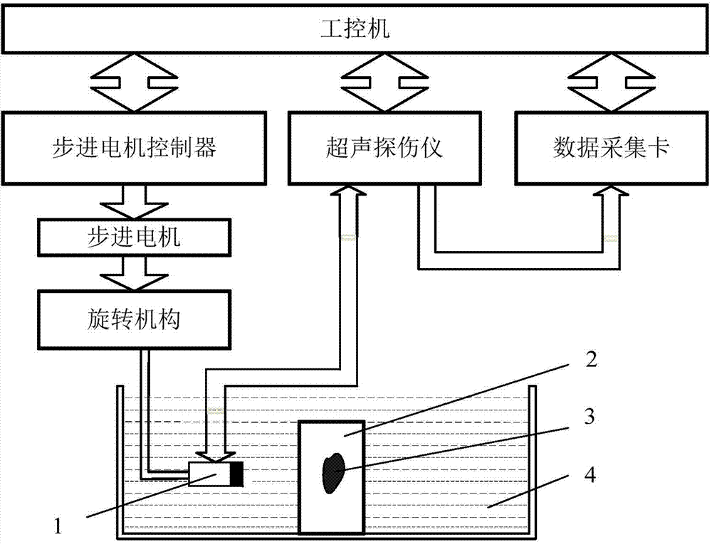
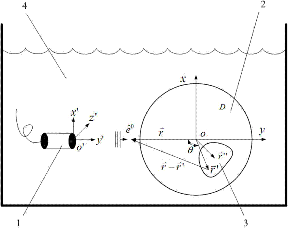
[0041] Such as figure 1As shown, the defect ultrasonic backscatter imaging device of the present invention includes an ultrasonic transducer 1, a rotating mechanism, a stepping motor, a stepping motor controller, a flaw detector, and a data acquisition card; the ultrasonic transducer is placed on the side of a cylindrical workpiece , and facing perpendicular to the central axis of the cylindrical workpiece 2, the coupling agent 3 is filled between the ultrasonic transducer and the cylindrical workpiece, the ultrasonic transducer is respectively connected to the rotating mechanism and the flaw detector, the rotating mechanism is connected to the stepping motor, and the stepping motor The controller is connected to the stepper motor for control, the flaw detector is connected to the data acquisition card, and the stepper motor controller, the flaw detector and the data ac...


PUM


Abstract

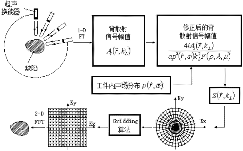
The invention discloses an ultrasonic back scattering imaging method and an ultrasonic back scattering imaging device for inner defects of a cylindrical workpiece. An ultrasonic energy converter is arranged towards the middle axis vertical to the cylindrical workpiece; a coupling agent is filled between the ultrasonic energy converter and the cylindrical workpiece; the ultrasonic energy converter can rotate along the middle axis and emits an incidence signal after rotating for an angle; the incidence signal is subjected to pulse echoes and then is received to obtain a defect back scattering signal; after the ultrasonic energy converter rotates for one circle, each signal is subjected to Fourier transform and is simulated through a sound field numerical value simulation method; the amplitude of the defect back scattering signal is compensated and then is put into a corresponding frequency domain space; then a Gridding meshing method is used for carrying out interpolation processing, and a rapid Fourier transform method is used for obtaining a defect image; and a series of defect images are overlapped to obtain three-dimensional image information. The ultrasonic back scattering imaging method has relatively detection cost, is simple to operate and can easily realize automation, and can be widely applied to automatic and quantitative detection of the cylindrical workpiece and materials.

Description

technical field [0001] The invention relates to a defect detection method of a workpiece, in particular to an ultrasonic backscatter imaging method and device for defects in a cylindrical workpiece. Background technique [0002] Cylindrical workpieces such as shafts and bars are widely used in the fields of national economy and national defense construction. During the manufacturing process of the workpiece and the subsequent use process, there may be defects inside the workpiece. If the defect cannot be detected in time, it will cause immeasurable consequences to the safety of people's lives and property. Although there are many types of non-destructive testing techniques, due to the continuous improvement of the reliability of ultrasonic non-destructive testing technology, coupled with its incomparable advantages in terms of safety, applicability, and richness of characteristic parameters, this technology has become an application in the field of non-destructive testing. ...

Claims


Application Information

Patent Timeline
IPC IPC(8): G01N29/06G01N29/265G01N29/44G01N29/46
Inventor 周红明金挺茅振华余松青周闻青
Owner ZHEJIANG MEASUREMENT SCI RES INST
Learn More