
Fluorescent microscopic image rebuilding method and system based on space variation point spread function

A point spread function, microscopic image technology, applied in the field of computer vision and image processing, can solve problems such as difficulty in accurately depicting PSF, different optical properties, deviation, etc., to achieve the effect of overcoming local shortcomings

Inactive Publication Date: 2015-07-01
BEIJING TECHNOLOGY AND BUSINESS UNIVERSITY
View PDF5 Cites 16 Cited by
  • Summary
  • Abstract
  • Description
  • Claims
  • Application Information

AI Technical Summary

Problems solved by technology

The experimental method is to image fluorescent beads with a diameter of less than 200 nanometers through an optical microscope. This method has high reliability in obtaining PSF, but the PSF of the actual microscopic imaging system is related to the optical properties of the biological sample itself, and different The optical properties of biological samples are different, so direct measurement is difficult to accurately describe the accurate PSF in actual microscopic imaging
In addition, due to the small geometric size of the fluorescent beads, the signal-to-noise ratio is relatively low during measurement, which requires the optical system to be adjusted to an ideal state as much as possible, but in the actual experimental environment, this state is difficult to achieve
The theoretical method is to bring parameters such as light wavelength, sample refractive index, and numerical aperture of the imaging device into the classical diffraction theoretical formula of Gibson S.F. and Lanni F., and then calculate the PSF, but because there are many parameters required in the formula, and In practice, some parameters are sometimes difficult to obtain accurately and are volatile, so the PSF obtained by the theoretical method often deviates from the actual situation

Method used


Image

  • Fluorescent microscopic image rebuilding method and system based on space variation point spread function
  • Fluorescent microscopic image rebuilding method and system based on space variation point spread function
  • Fluorescent microscopic image rebuilding method and system based on space variation point spread function

Examples


Embodiment Construction

[0025] In describing the present invention, it should be understood that the terms "center", "longitudinal", "transverse", "length", "width", "thickness", "upper", "lower", "front", " Back", "Left", "Right", "Vertical", "Horizontal", "Top", "Bottom", "Inner", "Outer", "Clockwise", "Counterclockwise", "Axial", The orientation or positional relationship indicated by "radial", "circumferential", etc. is based on the orientation or positional relationship shown in the drawings, and is only for the convenience of describing the present invention and simplifying the description, rather than indicating or implying the referred device or element Must be in a particular orientation, be constructed in a particular orientation, and operate in a particular orientation, and therefore should not be construed as limiting the invention.

[0026] In addition, the terms "first" and "second" are used for descriptive purposes only, and cannot be interpreted as indicating or implying relative impo...


PUM


Abstract

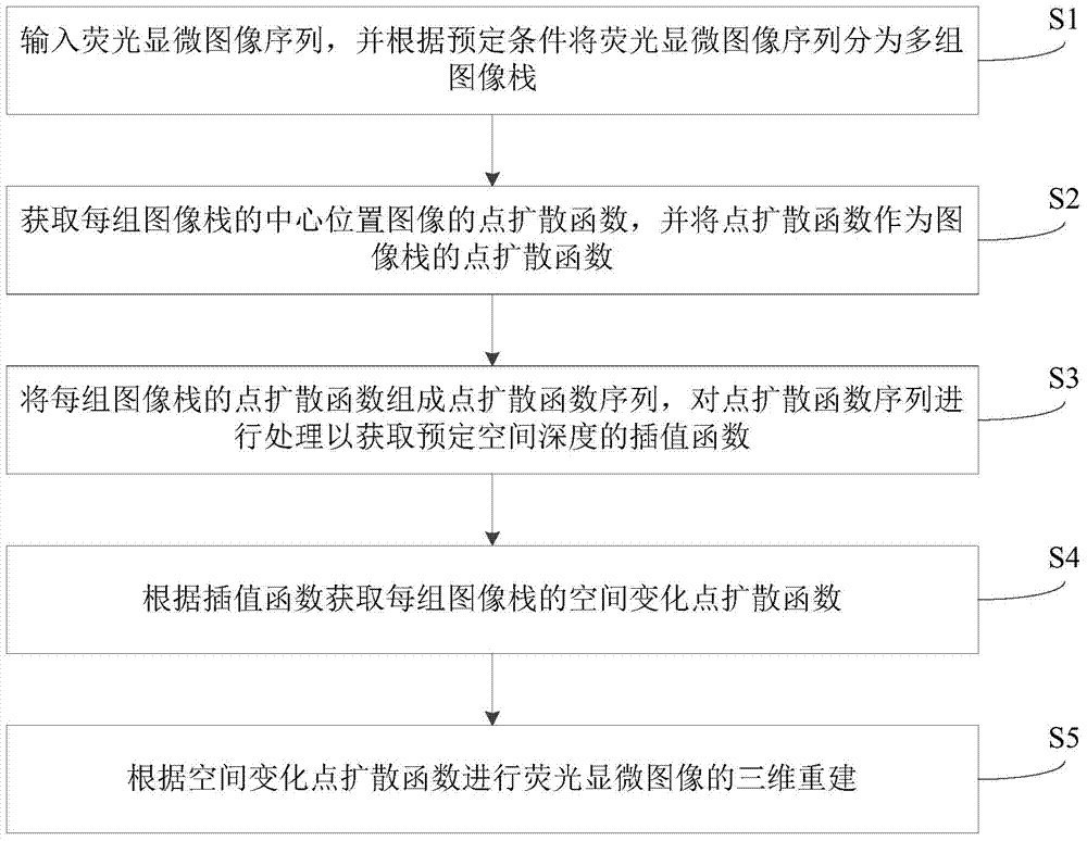
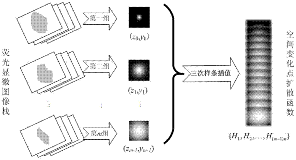
The invention provides a fluorescent microscopic image rebuilding method based on a space variation point spread function. The method comprises the following steps: S1, inputting a fluorescent microscopic image sequence, and dividing the fluorescent microscopic image into a plurality of groups of image stacks according to a preset condition; S2, obtaining a pot spread functions of images in the central positions of each group of image stacks, and taking the point spread functions as the point spread functions of the image stacks; S3, forming a point spread function sequence by the point spread functions of each group of image stacks, and processing the point spread function sequence to obtain an interpolation function of a preset spatial depth; S4, obtaining the spatial point spread functions of each group of image stacks according to the interpolation function; S5, carrying three-dimensional rebuilding of the fluorescent microscopic image according to the spatial point spread functions. The method provided by the invention is good in integrity and high in interpolation function. The invention further provides a fluorescent microscopic image rebuilding system based on the space variation point spread function.

Description

technical field [0001] The invention relates to the technical fields of computer vision and image processing, in particular to a method and system for reconstructing fluorescent microscopic images based on spatially varying point spread functions. Background technique [0002] As a challenging task in the field of computer vision and image processing, 3D restoration or reconstruction of fluorescence microscopic images has great value in biological, medical and life science research. However, due to the limitations of the diffraction of the optical imaging device itself, the limited numerical aperture and other factors, there is a certain degree of blurring in the formed image, which is characterized by a point spread function (PSF). This blurring becomes more serious as the imaging depth increases. [0003] At present, many technologies can realize 3D image reconstruction of biological samples, and have been continuously improved and perfected. To simplify calculations, so...

Claims


Application Information

Patent Timeline
IPC IPC(8): G06T5/00
Inventor 王瑜姜欢
Owner BEIJING TECHNOLOGY AND BUSINESS UNIVERSITY
Learn More