
Automatic ultrasonic testing equipment for threaded hole zone of nuclear reactor pressure vessel

A pressure vessel and ultrasonic inspection technology, which is applied in nuclear reactor monitoring, reactors, nuclear engineering, etc., can solve the problems of no automatic inspection equipment, low quantification of inspection data, and increase the exposure dose of inspectors, so as to reduce the exposure dose and pollution risks, strong data quantification, and the effect of saving inspection time

Active Publication Date: 2015-07-01
CHINA NUCLEAR POWER OPERATION TECH +1
View PDF5 Cites 18 Cited by
  • Summary
  • Abstract
  • Description
  • Claims
  • Application Information

AI Technical Summary

Problems solved by technology

2. The threaded hole on the flange surface and the contact belt between the holes. Since the upper surface of the threaded hole end plug cannot be guaranteed to be flat with the flange surface, the current inspection of this part is mainly manual inspection or semi-automatic manual inspection through a long rod. This method is not only inefficient, but also the quantitativeness of the inspection data is low, and if it is an in-service inspection, it will increase the exposure dose of the inspectors
[0004] At present, there is no equipment that can automatically check the above-mentioned measured objects

Method used


Image

  • Automatic ultrasonic testing equipment for threaded hole zone of nuclear reactor pressure vessel
  • Automatic ultrasonic testing equipment for threaded hole zone of nuclear reactor pressure vessel
  • Automatic ultrasonic testing equipment for threaded hole zone of nuclear reactor pressure vessel

Examples


Embodiment Construction

[0023] The present invention will be further described below with reference to the drawings and embodiments.

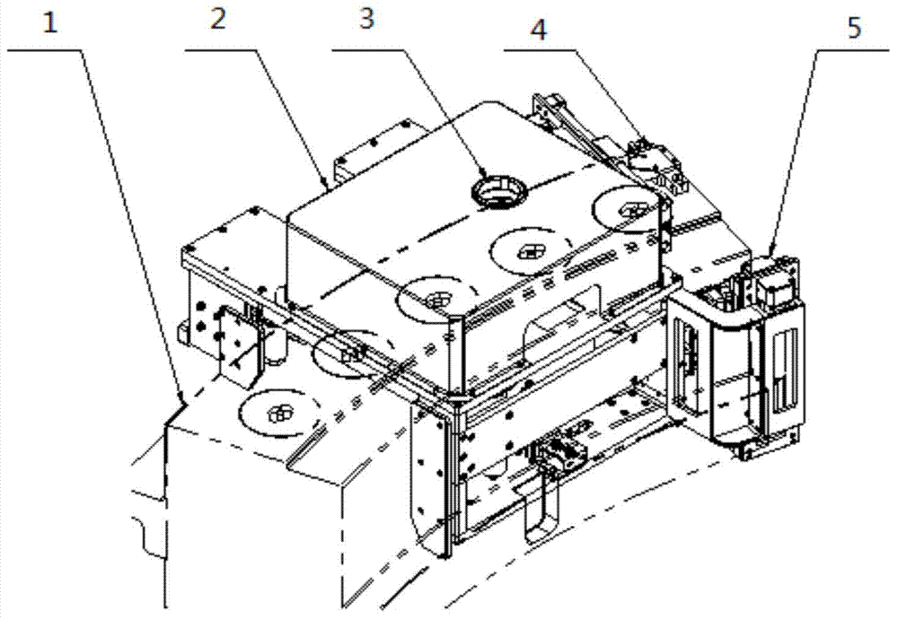
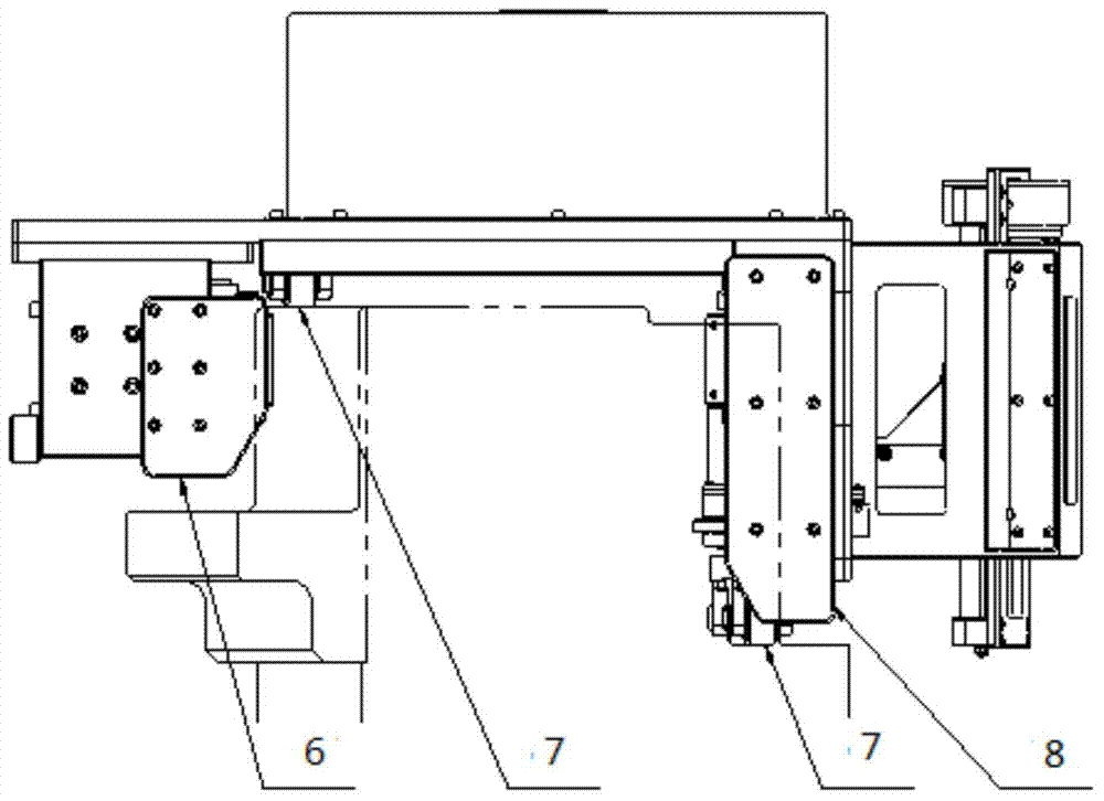
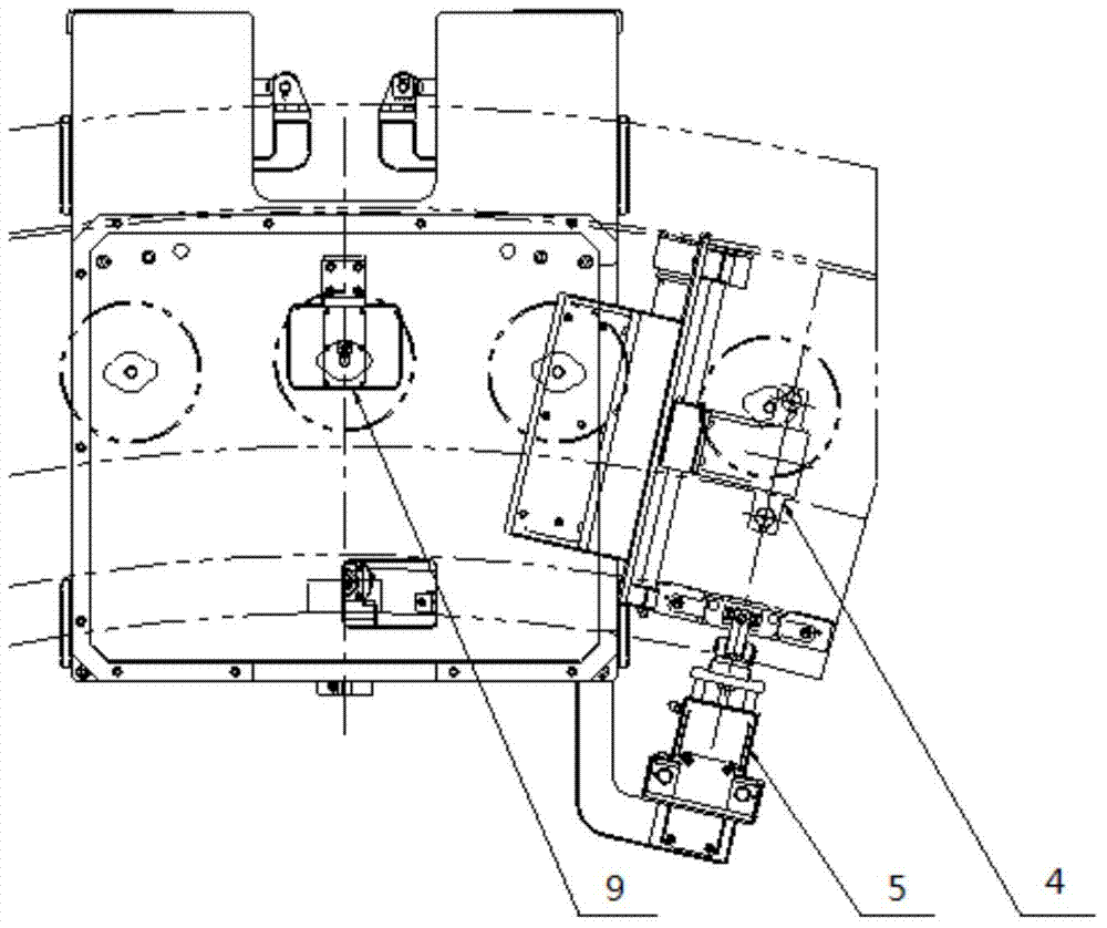
[0024] The automatic ultrasonic inspection equipment and principle of the threaded hole of the nuclear reactor pressure vessel involved in the present invention are as follows figure 1 , figure 2 , image 3 with Figure 4 Shown. Automatic ultrasonic inspection equipment for threaded holes of nuclear reactor pressure vessels includes: frame 2, lifting head 3, radial scanning assembly 4, axial scanning assembly 5, outer guide plate 6, vertical support wheel assembly 7, inner guide plate 8, The laser camera assembly 9, the driving wheel assembly 10, the encoder assembly 11, the circumferential support wheel assembly 12, the circumferential top pinch wheel assembly 13, the LED lamp 15, the camera 16 and the in-line laser 17.

[0025] The invention includes the following parts:

[0026] 1 Hoisting mechanism: the hoisting head 3 is installed on the frame 2. When checking the in...


PUM


Abstract

The invention belongs to the field of a non-destructive testing technology for a nuclear power station and in particular relates to automatic ultrasonic testing equipment for a threaded hole zone of a nuclear reactor pressure vessel. The automatic ultrasonic testing equipment comprises a rack (2), a vertical supporting wheel assembly (7), a driving wheel assembly (10), an encoder assembly (11), a circumferential supporting wheel assembly (12) and a circumferential pushing-against wheel assembly (13), wherein the rack (2) is arranged horizontally, is a main body structure of the automatic ultrasonic testing equipment for the threaded hole zone of the nuclear reactor pressure vessel, and is used for bearing all functional assemblies; and the vertical supporting wheel assembly (7) comprises multiple vertical supporting wheels which are arranged under the rack (2) for supporting the rack (2) in the pressure vessel. The automatic ultrasonic testing equipment is applied to automatic ultrasonic testing on an internal thread of the threaded hole zone of the nuclear reactor pressure vessel, connection zones of bolt holes and connection zones of the bolt holes in the inner side of the pressure vessel barrel, and is also used for nondestructive testing on the position of a flange of the pressure vessel in the other fields or is used for cleaning threaded holes, and the like.

Description

Technical field [0001] The invention belongs to the technical field of non-destructive testing of nuclear power plants. Background technique [0002] The threaded hole belt of the nuclear reactor pressure vessel is located at the top of the pressure vessel, with a number of bolt holes evenly distributed on it, and the top cover of the pressure vessel is buckled on top and tightened with bolts and nuts during operation. The material properties of the bolt holes and the connection between the holes and the holes directly affect the reliability of the fastening of the pressure vessel and the top cover, and further affect the safety performance of the pressure vessel. According to ARSM requirements, regular non-destructive testing of the threaded hole strips of nuclear reactor pressure vessels is required. [0003] At present, the inspection on the threaded hole belt of pressure vessels at home and abroad is divided into two parts: 1. The threaded hole contact belt on the inner wall o...

Claims


Application Information

Patent Timeline
Patent Type & Authority Applications(China)
IPC IPC(8): G21C17/003
CPCG21C17/013Y02E30/30
Inventor 吴东栋王俊涛尹鹏
Owner CHINA NUCLEAR POWER OPERATION TECH
Learn More