Production method for sintered neodymium-iron-boron permanent magnets
A production method and technology of permanent magnets, applied in the direction of magnetic objects, inductance/transformer/magnet manufacturing, magnetic materials, etc., can solve problems that cannot be fundamentally solved, have a single easy magnetization direction, and cannot be overcome
- Summary
- Abstract
- Description
- Claims
- Application Information
AI Technical Summary
Problems solved by technology
Method used
Image
Examples
Embodiment 1
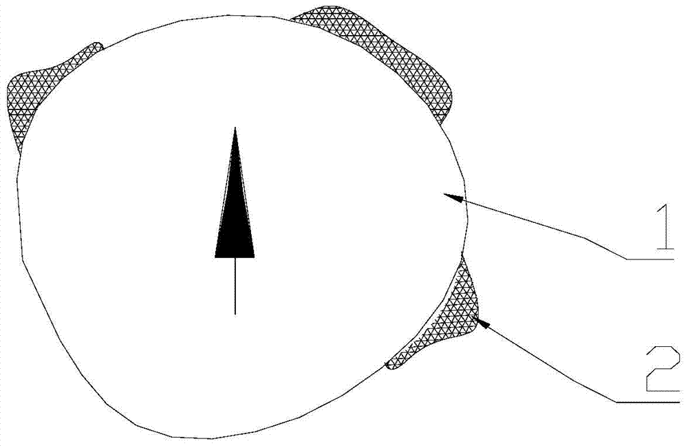
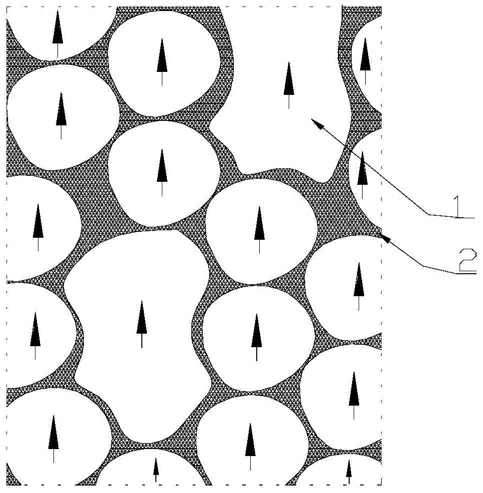
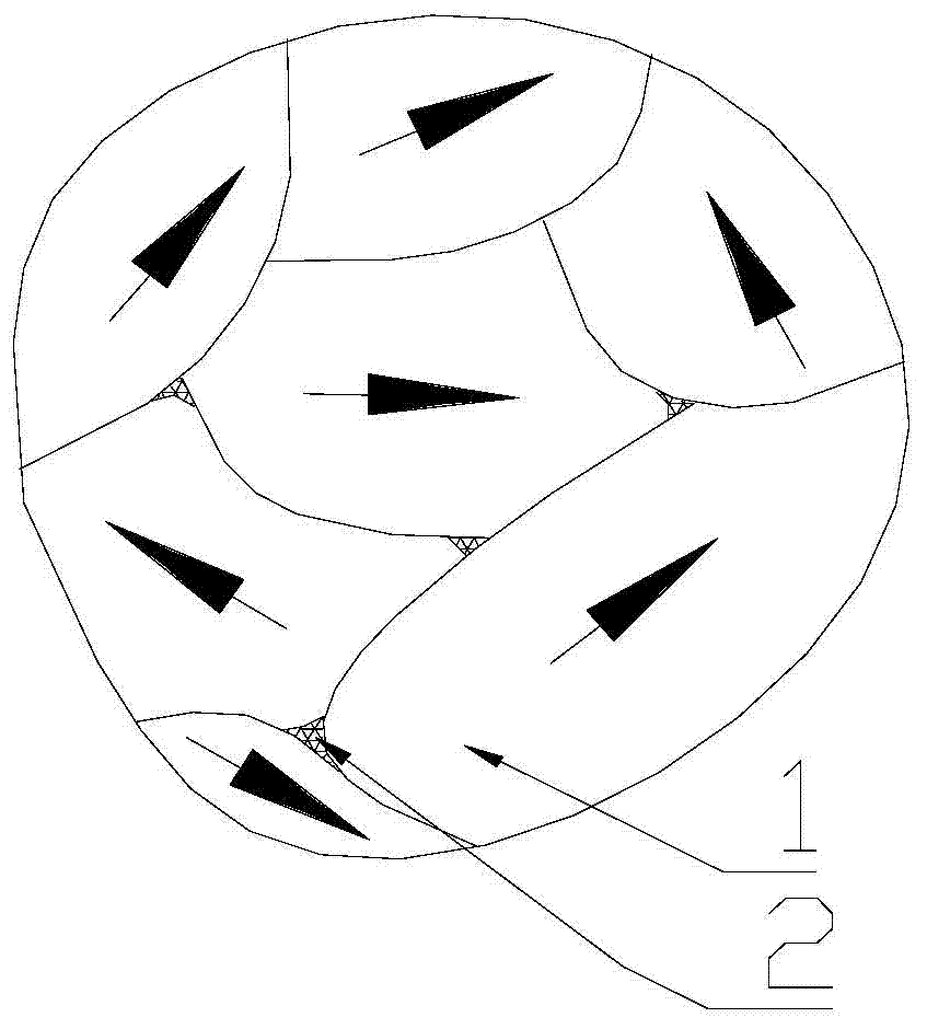
[0042] First, the ingredients are prepared according to the alloy A with the total rare earth content TRE=32.0wt.% in Table 1, and then the master alloy is made into a master alloy by the usual smelting method, and then the master alloy is hydrogenated and pulverized by a jet mill to form a master alloy powder. The grain size is 3.0~5.0μm; according to the alloy B with the total rare earth content TRE=26.8wt.% in Table 1, the ingredients are made, and the auxiliary alloy flakes are made by the quenching and smelting method, and the auxiliary alloy flakes are directly coarsely crushed and then jet milled Auxiliary alloy powder is obtained by crushing, and the grain size of the auxiliary alloy powder is 0.1-0.01 μm. The average particle size of the powders of alloy A and alloy B is 3.6 μm.
[0043] The powder of alloy A with a weight fraction of 98wt.% and the powder of alloy B with 2wt.% are fully mixed in a powder mixer, and then oriented under a magnetic field of 1.95T, 0.8t / ...
Embodiment 2
[0052] The preparation process, grain size and average particle size of the master alloy powder (alloy A powder) and auxiliary alloy powder (alloy B powder) used in Example 2 are exactly the same as those in Example 1. Mix 98wt.% Alloy A powder and 2wt.% Alloy B auxiliary powder in a powder mixer, orient under a magnetic field of 1.95T, 0.8t / cm 2 Compressed under pressure, sintered at 1070°C to form a magnet with a size of 51*51*25mm, and then tempered at 900°C and 480°C. The magnetic performance data of the fabricated magnets were measured, and the results are shown in Table 2.
Embodiment 3
[0058] The composition of 98wt.% is the same as the alloy A in Table 1, and the coarse powder obtained after the master alloy is made into a master alloy by a conventional smelting method is crushed in hydrogenation, and the composition of 2wt.% is the same as that of the alloy in Table 1. The coarse powder that is the same as in B, made into auxiliary alloy flakes by the quenching and smelting method without hydrogenation treatment, is fully mixed in the powder mixer, and then the mixture is pulverized by a jet mill, and the average particle size is 3.4 μm. of powder. Then oriented under 1.95T magnetic field, 0.8t / cm 2 Press molding, sintering at 1050°C to form a magnet with a size of 51*51*25mm, and then after secondary tempering at 900°C and 480°C, the magnetic performance data is measured with an automatic magnetic measuring device, as shown in Table 2.
[0059] It can be seen that compared with Comparative Example 1, the coercive force Hcj, maximum energy product (BH)m a...
PUM
| Property | Measurement | Unit |
|---|---|---|
| Grain size | aaaaa | aaaaa |
| Average particle size | aaaaa | aaaaa |
| Grain size | aaaaa | aaaaa |
Abstract
Description
Claims
Application Information
 - R&D
- Intellectual Property
- Life Sciences
- Materials
- Tech Scout
- Unparalleled Data Quality
- Higher Quality Content
- 60% Fewer Hallucinations
Browse by: Latest US Patents, China's latest patents, Technical Efficacy Thesaurus, Application Domain, Technology Topic, Popular Technical Reports.
© 2025 PatSnap. All rights reserved.Legal|Privacy policy|Modern Slavery Act Transparency Statement|Sitemap|About US| Contact US: help@patsnap.com


