Novel nano electrostatic siro-spinning method

A siro spinning, nano-level technology, applied in the field of nano-level electrostatic siro spinning, can solve the problems of low manufacturing efficiency and limited application fields, and achieve the effects of improving manufacturing efficiency, improving utilization rate and good evenness

Active Publication Date: 2015-07-08
SHANGHAI UNIV OF ENG SCI
View PDF10 Cites 12 Cited by
  • Summary
  • Abstract
  • Description
  • Claims
  • Application Information

AI Technical Summary

Problems solved by technology

[0004] The technical problem to be solved by the present invention is that the manufacturing efficiency of the existing electrospinning technology is low, and the application field is greatly limited

Method used


Image

  • Novel nano electrostatic siro-spinning method
  • Novel nano electrostatic siro-spinning method
  • Novel nano electrostatic siro-spinning method

Examples


Embodiment 1

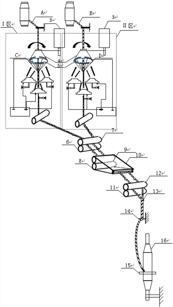
[0021] See attached figure 1 , the staple fiber rovings A and B unwound from two roving bobbins are fed in parallel into two electrospinning sections I and II between the feed roller and the roving hanger, in these two sections, both There is a motor 3 rotating at a certain speed to drive the horn-shaped receiver 4 for collecting nanofibers. The two horn-shaped receivers rotate separately to form an air flow. On the receiving ring 5 of the receiver, the deposited nanofiber bundle C is driven by the airflow to merge with the roving A flowing through the horn-shaped receiver; the nanofiber bundle D is merged with the roving B flowing through the horn-shaped receiver The two rovings drive the nanofibers into the rear drafting and twisting device in parallel, including rear roller 6, rear top roller 7, middle roller 8, middle top roller 9, apron 10, front roller 11, front top roller 12 After the two multi-component composite yarns are exported by the front roller, they are combin...

Embodiment 2

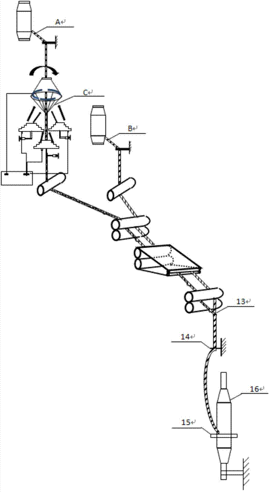
[0025] Such as Figure 2-Figure 3 As shown, the staple fiber rovings A and B unwound from two roving bobbins are fed in parallel to two electrospinning sections between the feed roller and the roving hanger. In this section, there are A motor rotating at a certain speed drives the horn-shaped receivers used for collecting nanofibers, and the two horn-shaped receivers rotate separately to form an air flow, and the nanofiber C is helically deposited on the receiving rings of the two horn-shaped receivers driven by the electric field force , the deposited nanofiber bundle C is driven by the airflow to merge with the roving A flowing through the horn-shaped receiver; the A roving drives the nanofibers into the rear drafting and twisting device in parallel, while the roving B directly enters the rear area Drafting and twisting device, after the two composite yarns of different components are exported by the front roller, they are merged at the joint point 13 and then twisted again,...

Embodiment 3

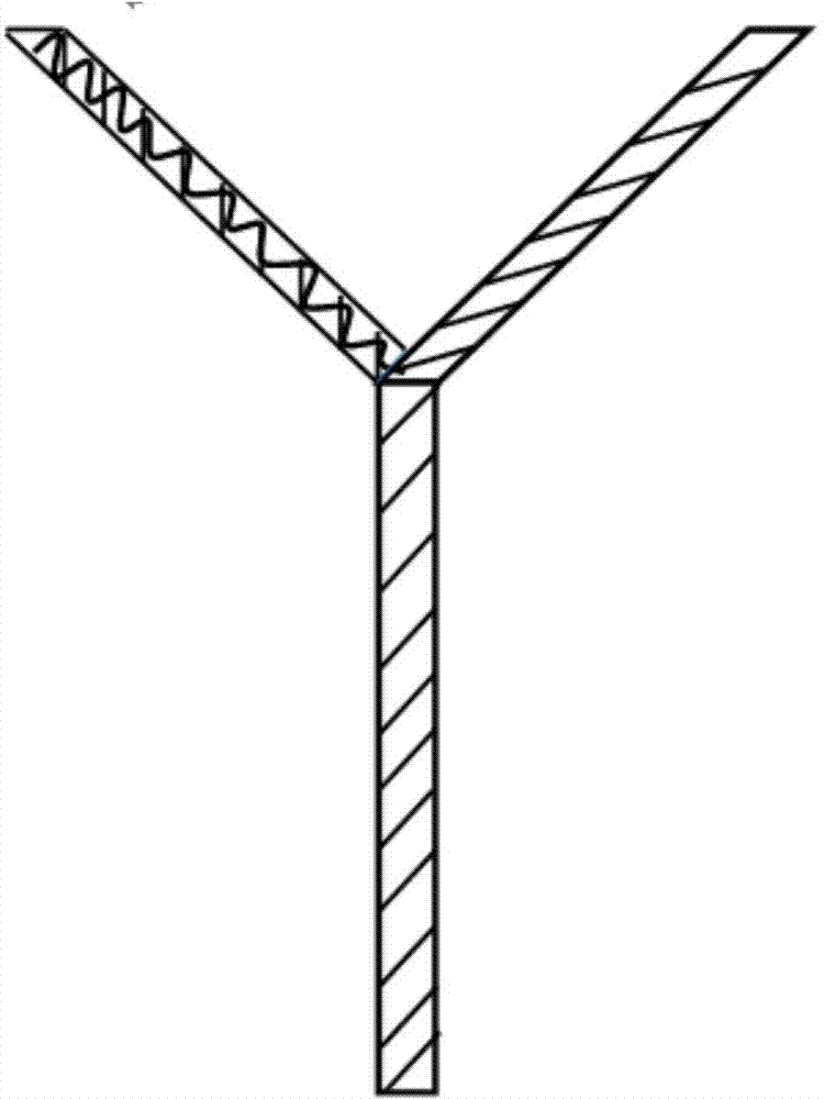
[0027] Such as Figure 4 As shown, the two strands are fed from the back roller of Siro spinning, pass through the middle roller, and the front roller is drafted and combined for output. An electrospinning device is installed between the front roller and the yarn guide hook. The electrospinning device is composed of a horn-shaped receiver, a material barrel, a pyramid-shaped spinneret, an electrostatic generator, a motor, and a chain. Driven by the electric field force, the fibers are spirally deposited on the receiver of the horn-shaped receiver. Driven by the airflow, the deposited nanofiber bundles are merged again with the merged roving flowing through the horn-shaped receiver, and passed through the yarn guide hook and steel wire. The coil is wound on the spun yarn tube, and the outer layer of the core-spun yarn that is finally drawn out contains nanofibers, which increases the hygroscopicity, oil absorption and filtration performance of the yarn.


PUM


Abstract

The invention relates to a novel nano electrostatic siro-spinning method. The method is that short-fiber rough yarns A and B recoiled from two rough yarn blocks are fed in parallel between two electrostatic spinning areas formed between a feeding roller and a rough yarn lifting rack; the two areas are provided with loudspeaker-shaped receivers which rotate at a certain of speed and driven by motors to collect nano fibers; the two loudspeaker-shaped receivers respectively rotate to form airflows; the nano fibers C and D are driven by electric field power to spirally deposit on receiving rings of the two oudspeaker-shaped receivers; a nano fiber bundle C deposited under the driving of the airflows is combined with the rough yarns A flowing through the loudspeaker-shaped receivers; a nano fiber bundle D is combined with the rough yarns B flowing through the loudspeaker-shaped receivers; the two rough yarns respectively drive each nano fiber to enter in parallel into rear stretching twisting devices; two multi-component combined yarns are guided out through front rollers and combined at a combining point and then twisted again, and finally the rough yarns pass through a steel wire rope through yarn guide hooks to coil the fine yarn blocks with self rotating power.

Description

technical field [0001] The invention relates to a spinning device, in particular to a nanoscale electrostatic siro spinning method, which belongs to the technical field of spinning. Background technique [0002] Siro spinning is a spinning method that spins yarns with a structure similar to strands on a traditional ring spinning frame. It feeds two rovings at a certain distance on the spinning frame, and after drafting, the front roller outputs the yarn. Two single yarn strands have a small amount of twist due to the transfer of twist, and are further twisted into a ply-like yarn after being combined and wound on the bobbin. This process ensures that the fibers are firmly locked into the structure of the yarn, giving the yarn a smooth finish that resists continuous friction and wear on the loom. [0003] The preparation of nanofiber materials by electrospinning technology is one of the most important academic and technical activities in the field of material science and tec...

Claims


Application Information

Patent Timeline
Patent Type & Authority Applications(China)
IPC IPC(8): D01H1/02D01H5/72
CPCD01H1/02D01H5/72
Inventor 辛斌杰奚桐
Owner SHANGHAI UNIV OF ENG SCI
Why Eureka
Try Eureka