
Solar heating photothermal collecting receiving device

A technology of receiving device and solar energy, which is applied in the direction of solar thermal device, solar thermal energy, solar thermal power generation, etc., can solve the problems of poor environmental adaptability and unsuitability for household use, complex structure of concentrating and collecting device, and low comprehensive efficiency utilization rate, etc. The effect of compact structure, light weight and simple structure

Inactive Publication Date: 2015-07-08
李博文
View PDF9 Cites 7 Cited by
  • Summary
  • Abstract
  • Description
  • Claims
  • Application Information

AI Technical Summary

Problems solved by technology

It can overcome the shortcomings of existing tracking devices of high-power concentrating solar collectors, such as complex structure, high energy consumption, low comprehensive efficiency utilization rate, poor environmental adaptability and unsuitable for household use, and proposes a simple and practical photovoltaic light Thermal mixing device
[0004] But the structure of the light concentrating collection device in the above-mentioned solar collection device is more complicated

Method used


Image

  • Solar heating photothermal collecting receiving device
  • Solar heating photothermal collecting receiving device
  • Solar heating photothermal collecting receiving device

Examples


Embodiment 1

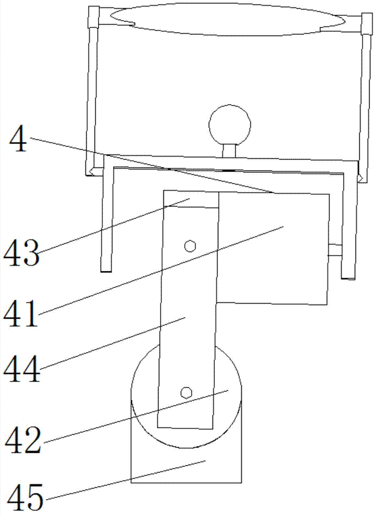
[0033] As the receiving device described above, the difference of this embodiment is that, refer to figure 2 As shown, it is a structural schematic diagram of Embodiment 1 of the present invention; the receiving device also includes a two-axis linkage automatic tracker 4, and the two-axis linkage automatic tracker 4 is connected with the support 3 for changing and adjusting the Fresnel lens 1 and the angle of the solar receiver 2.

[0034] The biaxial linkage automatic tracker 4 includes a first motor 41, a second motor 42, a motor support frame 43, two side plates 44 and a motor base 45, wherein one end of the first motor 41 is connected to the The bracket 3 is connected, and the other end is connected with the motor support frame 43 for adjusting the angle of the Fresnel lens 1 and the solar receiver 2 in the east-west direction; one end of the side plate 44 is connected with the motor support The frame 43 is connected, and the other end is connected with the second motor 42...

Embodiment 2

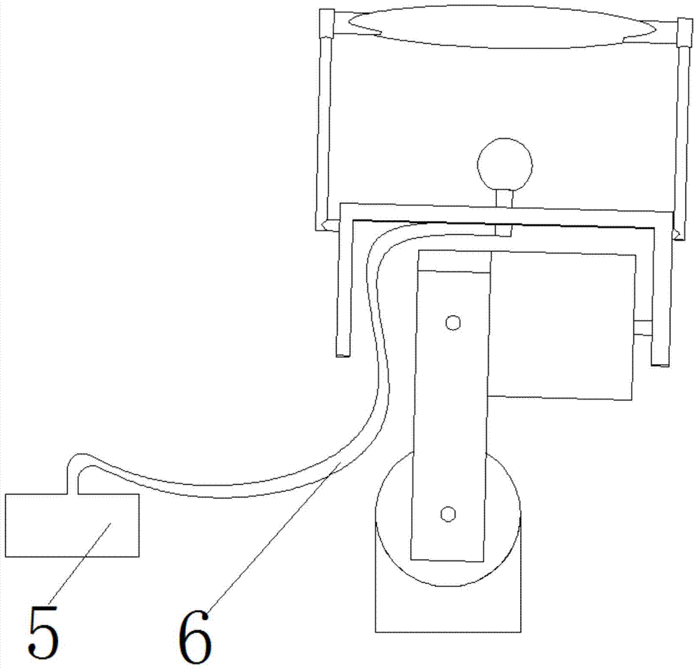
[0041] As the receiving device described above, the difference of this embodiment is that, refer to image 3 As shown, it is a schematic structural diagram of Embodiment 2 of the present invention; the receiving device also includes a heat pipe 5 and an energy storage tank 6, wherein one end of the heat pipe 5 is connected to the solar receiver 2, The other end is connected with the energy storage box 6 for conducting the heat energy received by the solar receiver 2 , and the energy storage box 6 is used for receiving and storing the heat energy transmitted by the heat pipe 5 .

[0042] The present invention uses the energy storage box 6 for thermal energy storage, solves the problem of using thermal energy without sunlight, achieves rational utilization of resources, and can also convert thermal energy into electrical energy for use in daily life and industry .


PUM

PropertyMeasurementUnit
Diameteraaaaaaaaaa
Diameteraaaaaaaaaa

Abstract

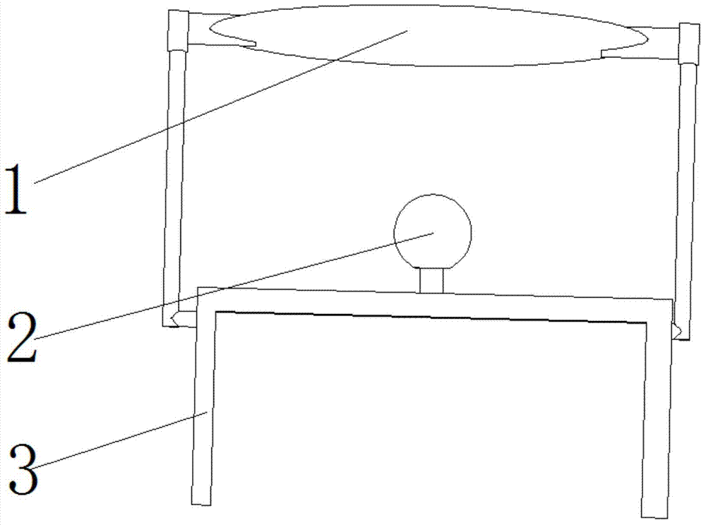
The invention provides a solar heating photothermal collecting receiving device. The receiving device comprises a Fresnel lens, a solar receiver and a support, wherein one end of the support is connected with the Fresnel lens, while the other end of the support is connected with the solar receiver; the Fresnel lens is used for focusing solar light; the solar receiver is used for receiving the solar light absorbed by the Fresnel lens. The solar heating photothermal collecting receiving device is high in solar energy utilization efficiency; the Fresnel lens is taken as the light condensing device and is excellent in light condensation property; the solar receiver is a pure copper sphere and capable of achieving the best heat transfer effect; besides, the pure copper sphere is relatively low in cost and has a use value; compared with the traditional lenses, the Fresnel lens has the advantages of large area, small volume, light weight, compact structure, relatively low cost, portability and the like, and is very suitable for the solar heating device; the receiving device is of a pure copper ball with relatively small volume.

Description

technical field [0001] The invention relates to a solar energy collecting device, in particular to a solar heating light-heat gathering and receiving device. Background technique [0002] Various gases and solid wastes during combustion and waste heat from power generation will cause pollution. The development and utilization of new energy has become a major issue that must be faced and solved in the long-term economic and social development of our country. As a sustainable and clean energy, solar energy is convenient and safe to use, and it will inevitably become one of the main energy sources for human beings. In recent years, its use in buildings has attracted great attention. In most parts of our country, the temperature is low in winter and heating is required. Affected by factors such as region, price, and resources, there are various types of existing heating forms. Mainly burn coal for heating, use electricity for heating and natural gas for heating. Coal has good ...

Claims


Application Information

Patent Timeline
IPC IPC(8): F24J2/08F24J2/38F24J2/34F24J2/48F24S23/30F24S50/20
CPCY02E10/47
Inventor 李博文门宝辉孙静李卓希李泽阳何楠王天宇
Owner 李博文
Learn More