Device and method for removing particles in nuclear reactor coolant

A technology for nuclear reactors and coolants, applied in nuclear engineering, radioactive purification, etc., can solve the problems of special working conditions and limitations of primary circuit pipelines, and achieve the effects of simple structure, low cost, and easy maintenance.

Inactive Publication Date: 2015-07-08
NORTH CHINA ELECTRIC POWER UNIV (BAODING)
View PDF4 Cites 1 Cited by
  • Summary
  • Abstract
  • Description
  • Claims
  • Application Information

AI Technical Summary

Problems solved by technology

At present, there are no good particle removal measures in China, and the working conditions of the primary circuit pipeline are special, and many particle removal measures will be limited under high temperature and high pressure conditions.

Method used


Image

  • Device and method for removing particles in nuclear reactor coolant
  • Device and method for removing particles in nuclear reactor coolant
  • Device and method for removing particles in nuclear reactor coolant

Examples


Embodiment 1

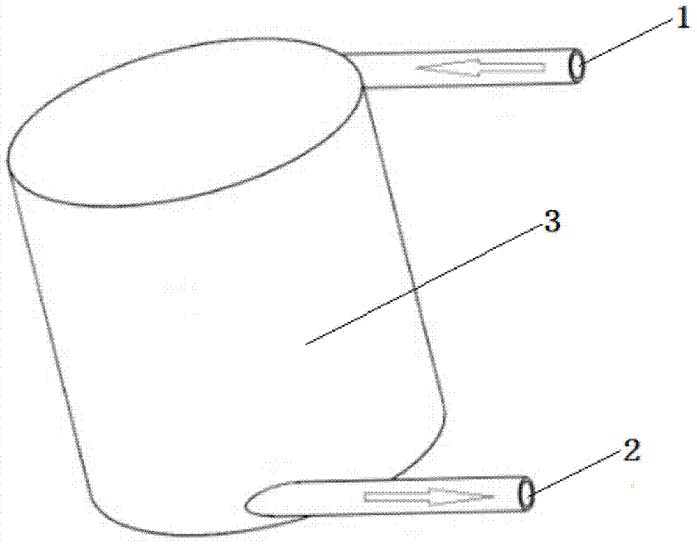
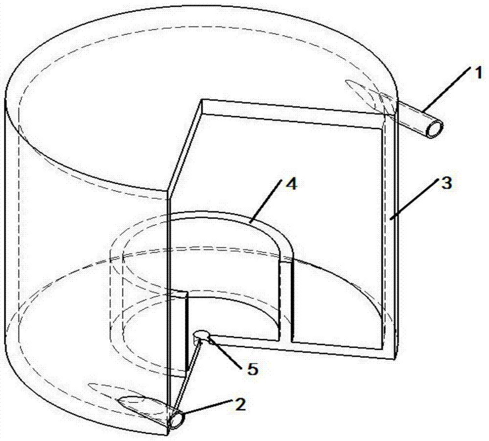
[0056] (1) The viscosity is 1095.1 μ Pa s, the particle volume fraction is 1.8%, and the heavy water whose fluid flow velocity is 2m / s is imported in the nuclear reactor coolant of the present invention from the fluid inlet pipeline of 0.02m according to a certain flow velocity. A device for removing particulate matter, the dimensions of the outer cylinder and the inner cylinder of the device are as follows:

[0057] The height of the outer cylinder is 2m and the diameter is 1m; the height of the inner cylinder is 0.1m and the diameter is 0.5m;

[0058] (2) After 5 minutes, take a sample from the fluid outlet pipeline with an internal diameter of 0.025m, and carry out the fine particle concentration test. The obtained result is: after passing through the removal device of the particle, the particle volume fraction in the fluid becomes 0.4%.

Embodiment 2

[0060] (1) the viscosity is 890.08 μ Pa s, the particle volume fraction is 2.5%, and the flow velocity is the water of 5m / s, from the fluid inlet pipeline of 0.04m input to two nuclear reactors according to the present invention connected in series from the inner diameter A device for removing particles in coolant, the dimensions of the outer and inner cylinders of the device are as follows:

[0061] The height of the outer cylinder is 3m and the diameter is 1.2m; the height of the inner cylinder is 0.2m and the diameter is 0.4m;

[0062] (2) After 5 minutes, take a sample from the fluid outlet pipeline with an internal diameter of 0.045m, and carry out the fine particle concentration test. The obtained result is: after passing through the removal device of the particle, the particle volume fraction in the fluid becomes 0.52%.

[0063] According to the experimental results, it is found that the device for removing particulate matter in the nuclear reactor coolant disclosed by ...


PUM


Abstract

The invention discloses a device for removing particles in a nuclear reactor coolant. The device comprises an outer barrel body, an inner barrel body, a liquid inlet pipeline, a liquid outlet pipeline, and a central hole formed in the bottom part of the inner barrel body, wherein the liquid inlet pipeline and the liquid outlet pipeline are arranged on the outer barrel body; the feeding speed and direction of liquid are basically consistent with the tangential line direction of the wall surface of the outer barrel body through the liquid inlet pipeline; liquid generates secondary flow while spirally moves; fine particles in the liquid can be continuously collected to the middle part of the outer barrel body under the effect of the secondary flow and can be deposited in the inner barrel body under the effects of turbulent flow and gravity; a discharging pipeline is arranged at the bottom part of the inner barrel body; when the fine particles are deposited to reach a certain of volume, a valve is opened to remove the deposited fine particles through the pipeline. The device has the characteristics of being safe, efficient, and safe in design and to control.

Description

technical field [0001] The invention relates to the field of nuclear power equipment, in particular to a device and method for removing particulate matter in nuclear reactor coolant. Background technique [0002] The coolant used in a large number of nuclear reactors, some impurity particles will inevitably exist in some coolants. In addition, when the reactor is running, it will cause corrosion and erosion of fuel rods, reactor internals and other components, so many fine particles will also be produced. These fine particles will enter the primary circuit as the "main artery" of the pressurized water reactor nuclear power plant along with the coolant, and the fine particles will deposit in the pipes, which will cause uneven heat transfer in the pipes and affect heat transfer efficiency, and will affect the service life of the entire primary circuit pipeline, which is related to the safe operation of the entire nuclear power plant. [0003] At present, the removal of fine p...

Claims


Application Information

Patent Timeline
Patent Type & Authority Applications(China)
IPC IPC(8): G21F9/20
CPCG21F9/20
Inventor 周涛方晓璐杨旭
Owner NORTH CHINA ELECTRIC POWER UNIV (BAODING)
Why Eureka
Try Eureka