A DC Power Flow Controller

A DC power flow and controller technology, applied in the direction of power transmission AC network, etc., can solve the problem of many switching devices, achieve the effects of fewer switching devices, simple circuit structure, improved control ability and transmission line transmission capacity

Active Publication Date: 2017-01-25
SOUTHEAST UNIV
View PDF1 Cites 0 Cited by
  • Summary
  • Abstract
  • Description
  • Claims
  • Application Information

AI Technical Summary

Problems solved by technology

However, the circuit structure of these two schemes requires an external power supply to provide power for the adjustable voltage source or absorb its power, and a low-frequency high-voltage isolation transformer is required for voltage isolation, and more switching devices are required.

Method used


Image

  • A DC Power Flow Controller
  • A DC Power Flow Controller
  • A DC Power Flow Controller

Examples


Embodiment Construction

[0022] The present invention will be further described below in conjunction with the accompanying drawings.

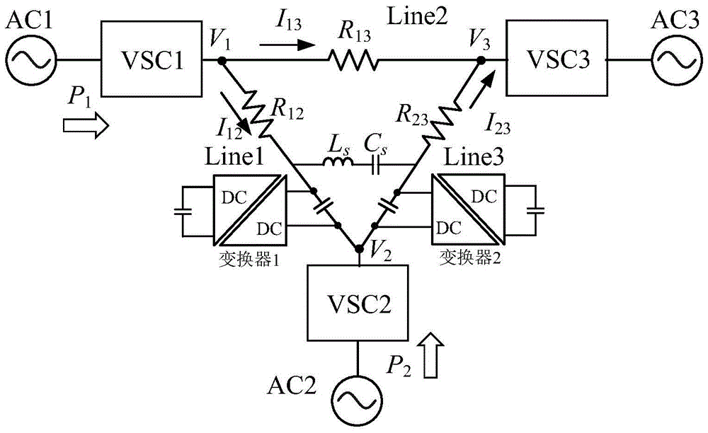
[0023] The present invention is applicable to multi-terminal (three-terminal and more than three-terminal) high-voltage direct current transmission systems, and the following only takes three-terminal direct current transmission systems as an example to describe in detail.

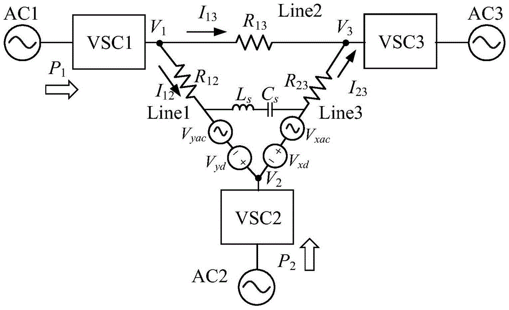
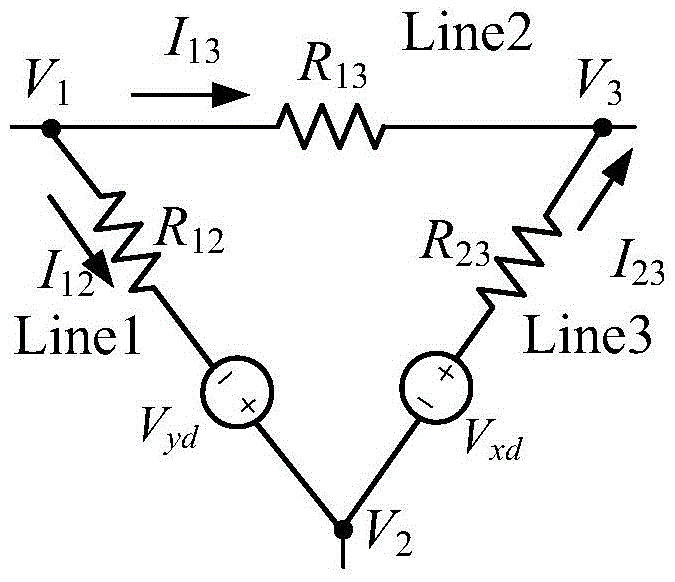
[0024] A three-terminal DC power transmission system comprising a DC power flow controller of the present invention such as figure 1 As shown, VSC3 operates in constant DC voltage mode, and VSC1 and VSC2 operate in constant power mode. The DC power flow control scheme includes two converters, and the converters are installed in the converter station VSC2. The output of the converters (V x and V y ) are respectively connected in series in the two transmission lines at VSC2. The equivalent circuit of the three-terminal DC transmission system including the DC power flow control method of the presen...


PUM


Abstract

The invention discloses a direct-current power flow controller which is suitable for multi-port direct-current transmission systems. The controller comprises two converters. The output ends of the converters are connected to different transmission lines in series. Each converter can output or absorb power in a direct-current mode and can also output or absorb power in an alternating-current mode at the same time. A band-pass filter between the two converters can limit power formed by alternating-current voltage and alternating current in an auxiliary passageway, and the alternating-current component on a direct-current transmission line can be effectively restrained. In this way, decoupling control over the power in a direct-current power ring and the power in an alternating-current power ring can be achieved, the direct-current power ring is specially used for power flow control over the direct-current transmission line, and the alternating-current power ring is used for power balance of the converters. According to the direct-current power flow controller, the structure of a circuit is simple, the number of switch devices is small, and a low-frequency isolation transformer and an external power source are not needed.

Description

technical field [0001] The invention relates to a novel direct current flow controller based on orthogonal power decoupling, which belongs to the technical field of power electronics and is mainly used in direct current transmission occasions. Background technique [0002] The multi-terminal direct current transmission system is a direct current transmission system consisting of three or more converter stations connected in series, parallel or hybrid. It can realize multi-source power supply and multi-drop power reception. The operation of the system is more economical and flexible, and it is one of the effective technical means to solve the large-scale renewable energy grid connection, large-capacity long-distance power transmission and the shortage of transmission corridors that our country is currently facing. Compared with the traditional current source converter, the voltage source converter (voltage source converter, VSC) reverses the direction of the DC current while ...

Claims


Application Information

Patent Timeline
Patent Type & Authority Patents(China)
IPC IPC(8): H02J3/36
CPCY02E60/60
Inventor 陈武吴小刚
Owner SOUTHEAST UNIV
Why Eureka
Try Eureka