A dds-based high-power signal transmission control method

A control method and signal transmission technology, applied in the direction of irreversible AC power input conversion to DC power output, output power conversion device, sustainable manufacturing/processing, etc., can solve the impact of instrument stability and reliability, peak shock pulse Large signal interference and other problems, to achieve stable amplitude, suppress peak interference, and low signal distortion

Active Publication Date: 2017-12-05
BC P INC CHINA NAT PETROLEUM CORP +1
View PDF2 Cites 0 Cited by
  • Summary
  • Abstract
  • Description
  • Claims
  • Application Information

AI Technical Summary

Problems solved by technology

[0003] The purpose of the present invention is to provide a high-power signal transmission control method based on DDS, to solve the problem that in the oil field development logging, the step wave in the high-power signal transmission has a large peak impact pulse signal interference in the inductive load, which affects the instrument stability and question of reliability

Method used


Image

  • A dds-based high-power signal transmission control method
  • A dds-based high-power signal transmission control method

Examples


Embodiment Construction

[0024] The technical solution of the present invention will be clearly and completely described below in conjunction with the accompanying drawings.

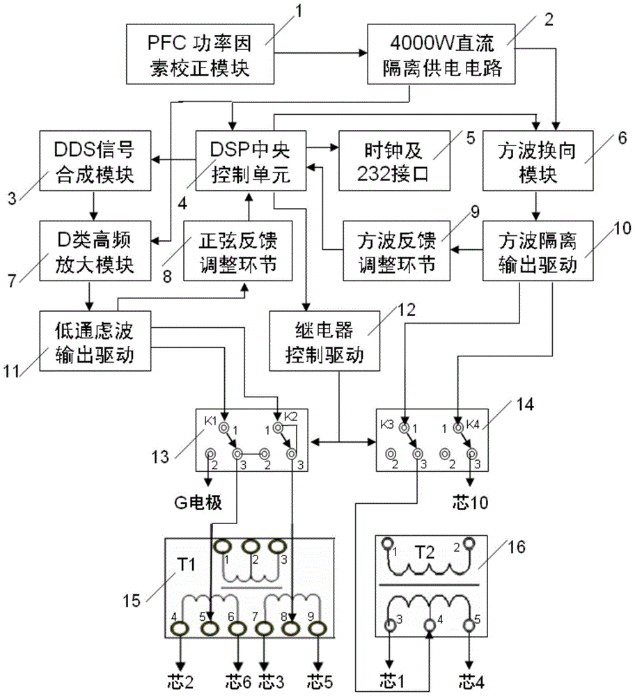
[0025] attached figure 1 It is a schematic diagram based on the high-power transmission control method. The flow of the control method from top to bottom consists of PFC power factor correction module 1, 4000W DC isolated power supply circuit 2, DDS signal synthesis module 3, DSP central control unit 4, clock and 232 interface 5 , square wave commutation module 6, class D high-frequency amplification module 7, sine feedback adjustment link 8, square wave feedback adjustment link 9, square wave isolation output drive module 10, low-pass filter output drive module 11, relay control drive module 12 , The first double-pole double-throw relay 13, the second double-pole double-throw relay 14, the mode transformer 15, the downhole power supply transformer 16 and so on.

[0026] The high-power transmission control method of the present...


PUM


Abstract

The invention discloses a high-power signal emission control method based on a DDS. A DDS synthesis technology is adopted, synthesis of emitted signals is controlled by a program, a digital technology D-class high-frequency amplification module is adopted, and therefore the distortion degree of the signals is low. A PFC technology is designed, and therefore the power factor of the high-power emitted signals is increased and the emission efficiency of the high-power emitted signals is improved. A step wave generation module is designed, an intelligent emission control mode is adopted, the efficiency of switching between sine waves and step waves is high, intelligent software delay of the time of the rising edge and the falling edge of the high-power step square wave signals effectively retrains peak pulse interference, an extremely-low-frequency and high-power emission function is achieved, and the frequency phase is stable. The high-power step square wave signals suffer little peak pulse interference on an inductive load, and the efficiency of intelligent high-power emission is high.

Description

technical field [0001] The invention relates to the field of petroleum logging, in particular to a DDS-based high-power signal transmission control method. Background technique [0002] Formation resistivity logging behind the casing is a logging method used to determine the remaining oil saturation of the reservoir during oilfield development, monitor the dynamic migration of oil and gas reservoirs, determine the oil saturation of the remaining oil in the reservoir, and optimize the oil well production plan. The magnitude of the emission current of the logging instrument is directly related to the measurement accuracy and the dynamic range of the reservoir resistivity measurement, which affects the accuracy of determining the oil saturation of the formation. The main difficulties are to improve the frequency and amplitude of the emission current signal and the size and accuracy There are: due to the influence of the skin effect of the steel casing, the frequency range of th...

Claims


Application Information

Patent Timeline
Patent Type & Authority Patents(China)
IPC IPC(8): H02M1/42H02M1/44H02M5/04H02M7/04
CPCY02B70/10Y02P80/10
Inventor 包德洲彭慧琴刘杰李妙侠李科安慰东任丽娟
Owner BC P INC CHINA NAT PETROLEUM CORP
Why Eureka
Try Eureka