

Continuous vacuum rapid quenching equipment and method for metal rapid quenching by using equipment
A vacuum and equipment technology, applied in the field of metallurgy, can solve the problems of lower production efficiency, blockage of injection holes, long time, etc., and achieve the effect of improving production efficiency and reducing time-consuming
- Summary
- Abstract
- Description
- Claims
- Application Information
AI Technical Summary
Problems solved by technology
Method used
Image

Examples
Embodiment 1
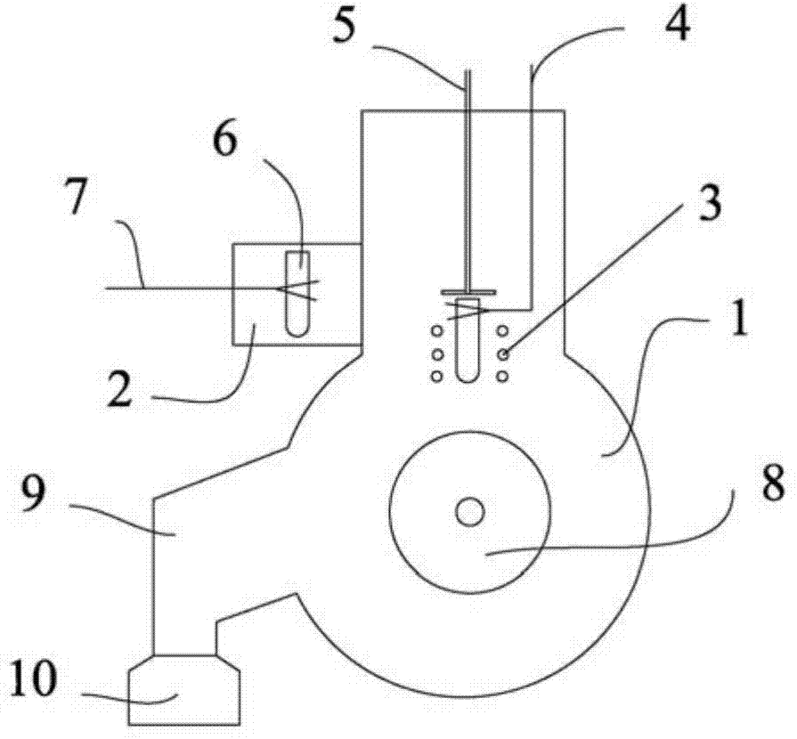
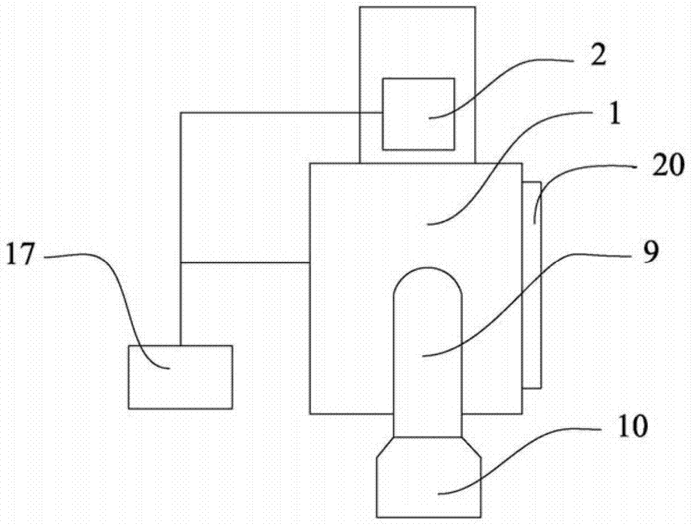
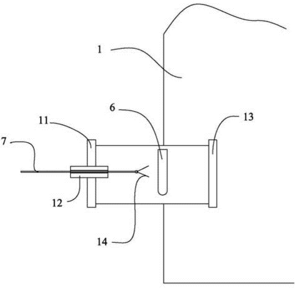
[0046] In this example, if figure 1 and 2 As shown, the continuous vacuum rapid quenching equipment includes a main chamber 1, which is used to fix the mechanical parts loaded inside it, and is isolated from the external environment such as air and water. The main cavity 1 is provided with a main cavity door 20, and the main cavity door 20 is opened when parts assembly or maintenance is required. In the working state, the main cavity 1 is sealed. A heating body 6, an induction coil 3, and a cooling device for rapid quenching are arranged in the main cavity 1 .
[0047] The heating body 6 is a crucible. The crucible is in the shape of a round cup with an inner diameter of 40-60 mm. The material of the crucible is one of alumina, magnesia, silicon carbide or quartz. The bottom of the crucible 6 has a leak hole with a diameter of about 1mm.
[0048] The appearance of the induction coil 3 is a spiral formed by hollow water-cooled copper tubes. The two ends of the copper tube p...
PUM
 Abstract
Description
Claims
Application Information