Device and method for measuring coaxiality
A coaxiality and detected technology, applied in the field of coaxiality measuring devices
- Summary
- Abstract
- Description
- Claims
- Application Information
AI Technical Summary
Problems solved by technology
Method used
Image

Examples
Embodiment 1
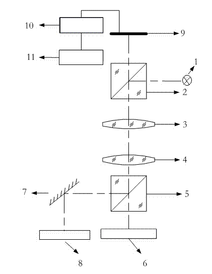
[0028] like figure 1 As shown, a device for measuring coaxiality includes a light source 1, and a beam-splitting prism 1 placed on the exit surface of the light source 1, and a lens 3, a beam-splitting prism 2, and a beam-splitting prism are sequentially arranged below the beam-splitting prism 1. A detected axis 6 is arranged below the second 5, a plane reflector 7 placed at a 45° angle is arranged on the left side of the dichroic prism two 5, and a detected axis two 8 is arranged below the plane reflector 7; above the dichroic prism one 2, there is A CCD detector 9 , the CCD detector 9 is electrically connected to a processor 10 , and the processor 10 is electrically connected to a computer 11 . The invention adopts a CCD detector with high quantum detection efficiency, high spatial resolution, high density resolution, high dynamic range, and can obtain the best image, the image quality is reliable and consistent for a long time, and the use cost is greatly reduced.
Embodiment 2
[0030] On the basis of embodiment 1,
[0031] The light source 1 of the present invention is a semiconductor laser point light source, and the semiconductor laser point light source has the characteristics of clarity, good consistency, and long service life; the lens one 3 and lens two 4 are convex lenses; the beam splitting prism one 2 and the beam splitting Prism 2 5 is a polarizing beam splitting prism with high extinction ratio.
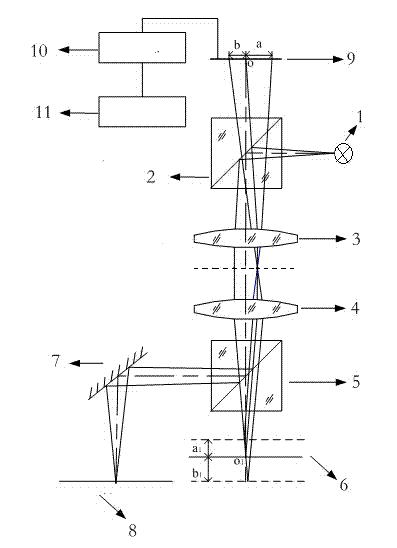
[0032] like figure 2 As shown, a method for measuring coaxiality comprises the following steps:
[0033] 1) Build the optical path, set the light source at the focal point of lens 1, so that the light beam emitted by the light source passes through the beam splitter prism 1 and lens 1 to form a parallel beam; when the lens 1 and lens 2 are set, the focus positions coincide; the parallel beams converge after passing through the lens 2 , and then transmitted through the second beam splitter prism to reach the axis one, the first axis is set at...
PUM
 Abstract
Description
Claims
Application Information
 - R&D
- Intellectual Property
- Life Sciences
- Materials
- Tech Scout
- Unparalleled Data Quality
- Higher Quality Content
- 60% Fewer Hallucinations
Browse by: Latest US Patents, China's latest patents, Technical Efficacy Thesaurus, Application Domain, Technology Topic, Popular Technical Reports.
© 2025 PatSnap. All rights reserved.Legal|Privacy policy|Modern Slavery Act Transparency Statement|Sitemap|About US| Contact US: help@patsnap.com