Polarizing plate

A technology of polarizers and polarizers, applied in the field of polarizers, can solve problems such as polarizers that have not yet been developed, achieve excellent thermal shock durability, and reduce the probability of cracks

Active Publication Date: 2015-07-15
DONGWOO FINE CHEM CO LTD
View PDF3 Cites 10 Cited by
  • Summary
  • Abstract
  • Description
  • Claims
  • Application Information

AI Technical Summary

Problems solved by technology

[0007] Therefore, the development of a polarizing plate having excellent thermal shock durability capable of suppressing such cracks is required, but such a polarizing plate has not actually been developed yet.

Method used


Image

  • Polarizing plate
  • Polarizing plate
  • Polarizing plate

Examples


manufacture example

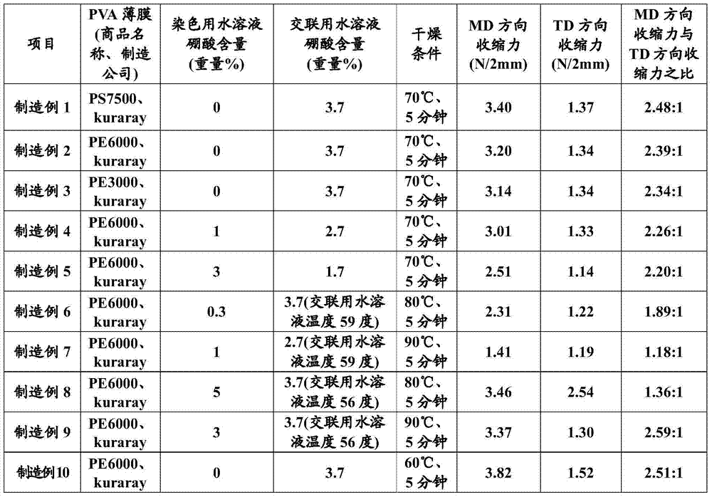
[0072] [production example, production of polarizer]

[0073] After soaking a polyvinyl alcohol film (PS 7500, Kuraray Co., Ltd.) with an average degree of polymerization of 2400, a degree of saponification of 99.9% or more, and a thickness of 75 μm in water (deionized water) at 30° C. for 2 minutes to swell, the It was dipped for 4 minutes in a 30° C. dyeing aqueous solution containing 3.5 mmol / L iodine and 2% by weight of potassium iodide to dye. Thereafter, it was dipped for 2 minutes in an aqueous solution for crosslinking at 53° C. to which 2% by weight of potassium iodide and 3.7% by weight of boric acid had been added to be crosslinked.

[0074] Thereafter, it was washed with distilled water at 25° C. for 20 seconds.

[0075] The cumulative draw ratio in each step of expansion / dyeing / crosslinking / water washing was 5.5 times, followed by heat treatment at 70° C. for 5 minutes to manufacture a polarizer (Manufacture Example 1).

[0076] Except for the conditions describ...

experiment example

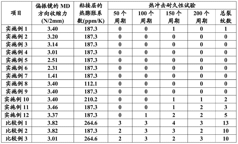
[0087] (1) Coefficient of thermal expansion (CTE) of the adhesive layer

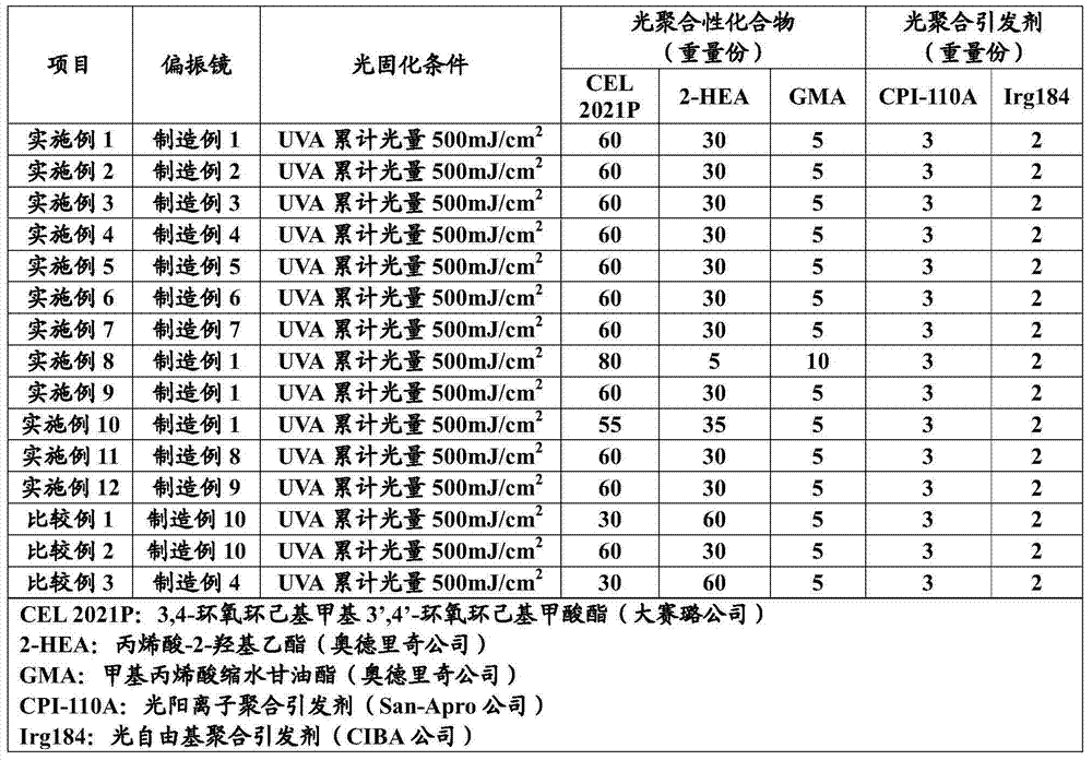
[0088] On a non-corona-treated cycloolefin polymer (COP) film (Zeon Corporation), the adhesive composition of the above-mentioned Table 2 was coated with a thickness of 30 μm by bar coating, and then a high-pressure mercury lamp ( The cumulative UVA light intensity is 500mJ / cm 2 ×4 times) for UV curing.

[0089] Next, after peeling off a 30 μm adhesive layer from the COP film and cutting it into a size of 8.0mm×4.0mm, the coefficient of thermal expansion was measured using TMA (TA Company) (the temperature was increased from 30°C to 10°C per minute under the measurement conditions). After reaching 70°C, the coefficient of thermal expansion was confirmed using the slope up to 70°C).

[0090] (2) Thermal shock durability test

[0091] After cutting the polarizers produced in Examples and Comparative Examples into a size of 15.0 cm (MD)×11 cm (TD), the polarizers were bonded to glass using an acrylic adh...


PUM

PropertyMeasurementUnit
thicknessaaaaaaaaaa
thicknessaaaaaaaaaa
thicknessaaaaaaaaaa

Abstract

The invention relates to a polarizing plate. The polarizing plate bonds a polarizer and a protective film through a bonding layer, the contraction force of the polarizer in the MD direction is lower than 3.5N/2mm, and the thermal expansion coefficient of the bonding layer is lower than 250ppm/K, and is between that of the polarizer and that of the protective film. Thus, the polarizing plate has significant excellent thermal shock durability, and the probability of crack generation is greatly reduced, even if the polarizing plate is exposed in high temperature and low temperature environments.

Description

technical field [0001] The present invention relates to a polarizer. Background technique [0002] A polarizing plate is useful as one of optical components constituting a liquid crystal display device. Generally, a polarizing plate has a structure in which protective films are laminated on both surfaces of a polarizer, and is mounted on a liquid crystal display device. It is known that a protective film is provided on only one side of a polarizer, but in most cases, instead of only providing a protective film on the other side of a polarizer, a layer having other functions such as an optical function doubles as a protection The film is attached to the other side. In addition, as a method of producing a polarizer, a method in which a uniaxially stretched polyvinyl alcohol-based resin film dyed with a dichroic dye is subjected to boric acid treatment, washed with water, and then dried is widely used. [0003] Usually, the protective film is attached to the polarizer immedi...

Claims


Application Information

Patent Timeline
Patent Type & Authority Applications(China)
IPC IPC(8): G02B5/30
CPCG02B5/3033B32B7/12C09J9/02G02B1/04G02B1/14G02F1/133528
Inventor 赵天熙金孝东崔允硕
Owner DONGWOO FINE CHEM CO LTD
Why Eureka
Try Eureka