Fast and efficient semiconductor laser cladding device with wide light beam and adjustable powder feeding angle

A laser cladding and semiconductor technology, which is applied to the surface treatment of semiconductor lasers. , In the field of fast and efficient semiconductor laser cladding devices, it can solve the problems of small increase in cladding area, high risk, and heavy burden on lathes, and achieve the effect of increasing single-pass cladding area, increasing cladding layer width, and reducing rotation burden

Active Publication Date: 2019-08-20
HUAZHONG UNIV OF SCI & TECH
View PDF6 Cites 5 Cited by
  • Summary
  • Abstract
  • Description
  • Claims
  • Application Information

AI Technical Summary

Problems solved by technology

However, because the high-speed laser cladding of small spot uses a circular small spot with a diameter of Φ1mm~2mm, although the cladding line speed is high, the area of ​​cladding per unit time is not greatly improved.
At the same time, the spot energy distribution used in small spot high-speed laser cladding usually satisfies the Gaussian distribution, which is characterized by high energy in a small area in the center of the spot, and rapid decline in energy away from the center. Due to the uneven energy distribution of the spot, a large amoun

Method used


Image

  • Fast and efficient semiconductor laser cladding device with wide light beam and adjustable powder feeding angle
  • Fast and efficient semiconductor laser cladding device with wide light beam and adjustable powder feeding angle
  • Fast and efficient semiconductor laser cladding device with wide light beam and adjustable powder feeding angle

Examples


Example Embodiment

[0036] In order to make the objectives, technical solutions and advantages of the present invention clearer, the following further describes the present invention in detail with reference to the accompanying drawings and embodiments. It should be understood that the specific embodiments described herein are only used to explain the present invention, but not to limit the present invention. In addition, the technical features involved in the various embodiments of the present invention described below can be combined with each other as long as they do not conflict with each other.

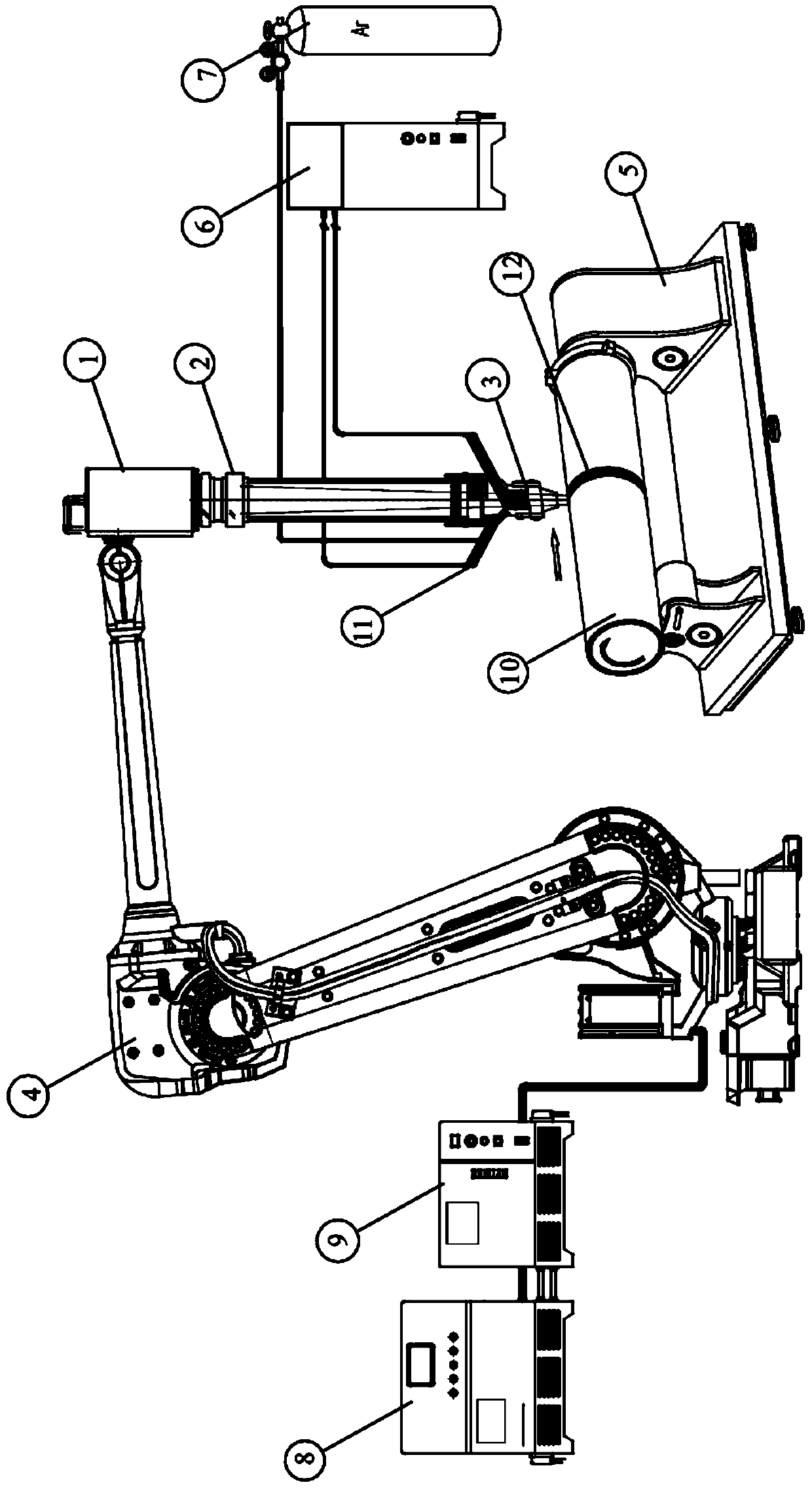
[0037] The purpose of the special device designed by the present invention is very clear, which is to solve the laser surface treatment device and process problem of the surface modification efficiency of the super large shaft workpiece, and can be applied to the surface of the large shaft workpiece with a diameter greater than 1000mm and a length of not less than 10m. Perform laser cladding treatment....


PUM


Abstract

The invention belongs to the technical field of laser surface modification, and discloses a fast and efficient semiconductor laser cladding device with a wide light beam and an adjustable powder feeding angle. The fast and efficient semiconductor laser cladding device with the wide light beam and the adjustable powder feeding angle comprises a semiconductor laser (1), a light beam shaping and Fresnel focusing system (2), an adjustable wide light band powder feeding head (3), a powder feeder (6), a high-speed machine tool (5), a six-axis linkage robot (4) and a central control system (9), wherein the light beam shaping and Fresnel focusing system (2) is used for shaping a laser light and focusing to form a wide-light-band laser light; the adjustable wide light band powder feeding head (3) is used for conveying powder and the wide-light-band laser light on the surface of a large-scale shaft type workpiece to be processed; and the diameter of a workpiece is larger than 1000mm, and the length of the workpiece is not lower than 10m. According to the fast and efficient semiconductor laser cladding device with the wide light beam and the adjustable powder feeding angle provided by the invention, through improving structures and arrangement manners of key components, outer surface strengthening and surface repairing can be carried out aiming at the large-scale shaft type workpieces such as petroleum pipelines, ocean facilities, natural gas conveying, mining and tunnel piercing, so that the wear resistance and the corrosion resistance of the surface are improved, and the service life is greatly prolonged.

Description

technical field [0001] The invention belongs to the technical field of laser surface modification of high-efficiency and high-power semiconductor lasers, more specifically, it relates to a fast and efficient semiconductor laser cladding device with wide beams and adjustable powder delivery angle, especially a method for super-large shaft workpiece surface semiconductor laser surface treatment. Background technique [0002] The super large hydraulic cylinder piston rod structure is widely used in various industrial fields such as oil pipelines, marine equipment, natural gas transmission, mining, and tunneling. Since the working environment of machinery is often in direct contact with sand and corrosive solutions, there are extremely high requirements for the corrosion resistance and wear resistance of the outer surfaces of large rod-shaped workpieces such as piston rods. Because once the wear-resistant and corrosion-resistant functions of such parts fail, the damage of the c...

Claims


Application Information

Patent Timeline
IPC IPC(8): C23C24/10
CPCC23C24/10
Inventor 唐霞辉罗惜照秦应雄邹翱张旭辉马豪杰范远超宋宇燕肖瑜万辰皓彭浩
Owner HUAZHONG UNIV OF SCI & TECH
Why Eureka
Try Eureka