Double-layer coil for electromagnetic formation and manufacturing method of double-layer coil

An electromagnetic forming and coil technology, which is applied in coil manufacturing, coils, circuits, etc., can solve the problems of high resistance of welding joints, influence on the overall strength of the coil, reduce winding density and number of turns, etc., achieve improved insulation and strength, and reduce inner wall Interference, the effect of increasing the winding density

Inactive Publication Date: 2015-07-15
FUZHOU UNIV
View PDF5 Cites 16 Cited by
  • Summary
  • Abstract
  • Description
  • Claims
  • Application Information

AI Technical Summary

Problems solved by technology

The main disadvantage of this coil is that the magnetic field density generated by only using a single-layer coil is limited. When the size of the electromagnetic riveting gun equipment is limited, the forming force is relatively small, and it is difficult to form a large-diameter rivet.
In addition, the coil also has the following disadvantages: the shell is separated from the support plate and connected with insulating resin, but the strength of the insulating resin is not high, which affects the overall strength of the coil; the countersunk nut is fixed on the side of the shell and connected with the power line, which will The inner wall of the riveting gun interferes, which increases the size of the riveting gun to a certain extent; the core tube and the copper strip, and the copper strip and the countersunk nut are connected by welding. When a large current is passed, the resistance of the welding joint is large and the heat is large, which affects the insulation of the coil. performance and longevity; copper tape insulation uses thicker glass fiber cloth, which reduces the winding density and number of turns

Method used


Image

  • Double-layer coil for electromagnetic formation and manufacturing method of double-layer coil
  • Double-layer coil for electromagnetic formation and manufacturing method of double-layer coil
  • Double-layer coil for electromagnetic formation and manufacturing method of double-layer coil

Examples


Embodiment Construction

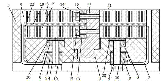
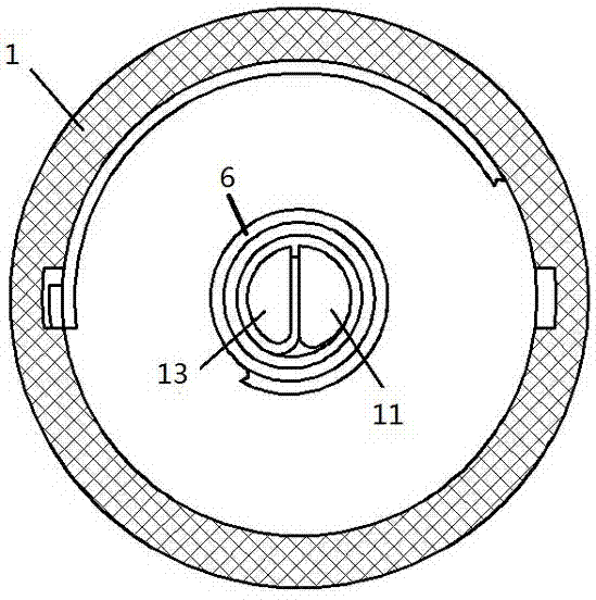
[0032] Such as Figure 1~5 As shown, the embodiment of the present invention provides a double-layer coil for electromagnetic forming, which includes a cylindrical shell 1, and the front of the shell 1 is provided with a circular groove 2 for placing the coil. An upper layer coil 6 and a lower layer coil 7 are sequentially arranged in the groove 2 from top to bottom, a rectangular through hole 5 is provided in the groove 2 close to the edge of the housing 1, and the middle part of the groove 2 is provided with There is a stepped blind hole 3 for placing an intermediate joint, the intermediate joint is matched with the stepped blind hole 3, and a rectangular first blind hole 4 is symmetrically provided on both sides of the stepped blind hole 3; The back of the housing 1 is provided with a second blind hole corresponding to the first blind hole 4, and the second blind hole is provided with an inclined side, and the first blind hole 4 and the second blind hole pass through a The...


PUM


Abstract

The invention relates to a double-layer coil for electromagnetic formation and a manufacturing method of the double-layer coil. The double-layer coil comprises a casing; a circular groove where coils are arranged is formed in the front side of the casing; an upper layer coil body and a lower layer coil body are sequentially arranged in the groove from top to bottom; two rectangular through holes are respectively formed in two sides, close to the edge of the casing, in the groove; a step blind hole where a middle connector is arranged is formed in the middle of the groove; the middle connector is matched with the step blind hole; rectangular first blind holes are symmetrically formed in the two sides of the step blind hole; second blind holes corresponding to the first blind holes are formed in the back side of the casing; the first blind holes are communicated with the second blind holes; the beginning end of the upper layer coil body and the beginning end of the lower layer coil body are connected with the middle connector; the output end of the upper layer coil body and the output end of the lower layer coil body penetrate through the through holes and then are respectively connected with a power line in the second blind holes electrically. The double-layer coil has the advantage that the insulation and the mechanical strength of the coil are improved.

Description

technical field [0001] The invention relates to a double-layer coil for electromagnetic forming, and also relates to a manufacturing method of the double-layer coil. Background technique [0002] Electromagnetic forming technology is mainly used in the aerospace field. The overall electromagnetic forming equipment includes electromagnetic forming energy storage system and external electromagnetic force generating device. Electromagnetic riveting is a specific application of electromagnetic forming technology. In the electromagnetic forming equipment, the coil is the most core component, and it is the key to convert electrical energy into magnetic field energy and then into mechanical energy, which directly affects the output of electromagnetic forming force. [0003] The electromagnetic forming force is closely related to the current and the number of turns of the coil. The greater the current passing through the coil, the greater the forming force. Therefore, it is necessar...

Claims


Application Information

Patent Timeline
Patent Type & Authority Applications(China)
IPC IPC(8): H01F5/00H01F41/04
Inventor 邓将华程溧詹艳然江星莹
Owner FUZHOU UNIV
Why Eureka
Try Eureka