Battery pack protection circuit, battery pack and electromotive tool

A technology for protecting circuits and battery packs, applied in battery circuit devices, emergency protection circuit devices, electric vehicles, etc., can solve the problems of increasing the difficulty of carrying, low function utilization, and high requirements for the working environment, and achieve strong market value , the effect of controlling manufacturing and design costs

Inactive Publication Date: 2015-07-15
POSITEC POWER TOOLS (SUZHOU) CO LTD
View PDF5 Cites 1 Cited by
  • Summary
  • Abstract
  • Description
  • Claims
  • Application Information

AI Technical Summary

Problems solved by technology

When designing a battery pack discharge protection circuit with multiple batteries, there are two conventional methods. One is to connect a single battery protection chip to each battery. Stopping the discharge of the entire battery pack, this protection method makes the number of single-cell protection chips larger, resulting in a larger battery pack protection circuit, resulting in a larger volume and weight of the battery pack or electrical device containing the battery pack protection circuit. It increases the difficulty of carrying and increases the design cost of the battery pack protection circuit; another method is to use an integrated microprocessor (MCU) to collect the output voltage and output current of the entire battery pack and judge the output voltage or output Whether the current meets the requirements, and then realize the discharge protection of the entire battery pack. However, the integration of the microprocessor (MCU) is relatively high. When it is used alone for the over-discharge or over-current protection of the battery pack, in addition The utilization rate of functions other than detection is low, and due to the limitation of microprocessor processing technology, its cost has always been high. At the same time, the microprocessor (MCU) is very delicate and has high requirements for its working environment, which is not conducive to this Popularization and Application of a Battery Protection Circuit

Method used


Image

  • Battery pack protection circuit, battery pack and electromotive tool
  • Battery pack protection circuit, battery pack and electromotive tool

Examples


Embodiment Construction

[0031] The present invention will be described in detail below in conjunction with specific embodiments shown in the accompanying drawings. However, these embodiments do not limit the present invention, and any structural, method, or functional changes made by those skilled in the art according to these embodiments are included in the protection scope of the present invention.

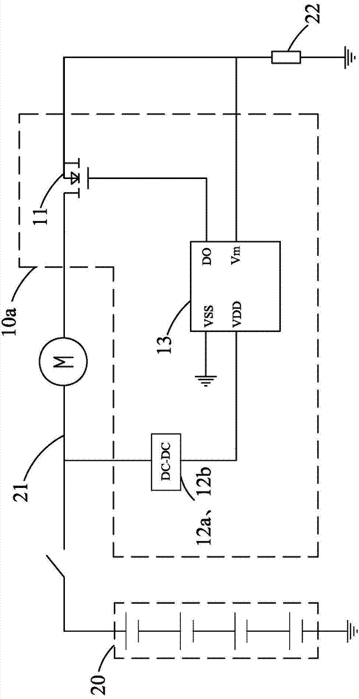
[0032] ginseng figure 1 As shown, in the first embodiment of the present invention, the battery pack protection circuit 10a can prevent the abnormal discharge of the battery pack 20 during the discharge process of the battery pack 20 and the electric tool (not shown), and ensure that the battery pack 20 and the safety of electrical components in electric tools.

[0033] It should be noted that the abnormal discharge of the battery pack 20 described herein refers to situations where over-discharge, over-current, and over-temperature of the battery pack 20 are likely to cause damage to the battery pack ...


PUM


Abstract

The present invention provides a battery pack protection circuit, which is configured to protect a battery pack with N batteries, wherein N is an integer greater than or equal to 2, and the battery pack is provided with an output circuit. The battery pack protection circuit comprises: a switch unit, connected in series in the output circuit; a single battery protection chip, configured to acquire output parameters of the battery pack and control switch-off of the switch unit upon judging that output parameters are not within a preset parameter range; and a power supply module, configured to acquire an output voltage of the battery pack, reduce voltage and supply power to the single battery protection chip. The single battery protection chip originally configured to protect a single battery and the power supply module, matched with each other, are expanded to discharging protection of the battery pack by the battery pack protection circuit, such that the costs of manufacturing and design of the battery pack protection circuit are reduced, the volume increment caused by the battery pack protection circuit is avoided, and very high market value is realized. In addition, the present invention provides a battery pack applying the protection circuit and an electromotive tool.

Description

technical field [0001] The invention relates to a battery pack protection circuit, a battery pack using the battery pack protection circuit and an electric tool. Background technique [0002] In recent years, with the development of battery material technology, the capacity of batteries has been greatly improved, and its application range has also extended from some low-power electronic electrical devices to some high-power power electrical devices, such as electric tools Wait. In this way, the electric tool using the high-rate battery can be freed from the shackles of cables and can be used anytime and anywhere. In order to improve the utilization rate, these batteries usually use rechargeable batteries, such as nickel-cadmium (Nickel-cadmium, NiCd) batteries, nickel-metal hydride (Nickel-Metal Hydride, NiMH) batteries, lithium-ion (Lithium-ion, L-ion) battery etc. [0003] The above-mentioned type of battery is in a discharge state when working with electric tools. When...

Claims


Application Information

Patent Timeline
Patent Type & Authority Applications(China)
IPC IPC(8): H02H7/18H02J7/00
Inventor 邓强罗杰
Owner POSITEC POWER TOOLS (SUZHOU) CO LTD
Why Eureka
Try Eureka