Multi-station material conveying system

A transmission system and multi-station technology, which is applied in the field of multi-station material transmission system, can solve the problems of scratching the material, affecting the grasping of the workpiece, and not being able to remove the material, so as to reduce the probability of falling and improve production Efficiency and workload reduction effect

Inactive Publication Date: 2015-07-22
HEBEI UNIV OF TECH +1
View PDF8 Cites 22 Cited by
  • Summary
  • Abstract
  • Description
  • Claims
  • Application Information

AI Technical Summary

Problems solved by technology

In the processing process of traditional stretched products, due to the many processes of processing stretched products, many molds, occupied equipment, and many operators, the processing is complicated, the cost is high, and the processing accuracy is low.
And most of the above-mentioned processes need manual operation, so that the production efficiency is low, the safety is poor, and the product quality is poor
[0003] The Chinese patent No. ZL201210100226.x discloses a stamping multi-station synchronous pneumatic manipulator, which can be used for mechanical handling. Its disadvantage is that the driving device uses a cylinder, which has poor stability and precision when moving, and may affect the workpiece during work. crawling
[0004] The Chinese patent No. ZL200910070055.9 discloses a multi-station material conveying manipulator. This invention is used for the stamping and forming process of the seal ring skeleton, and uses a rotary mechanism for material handling. One station, and through the cooperation of the positioning sleeve and the positioning pin to realize the opening and closing of the electromagnetic chuck mechanism and the rotary disc, the electromagnetic chuck may magnetize the material during the process of absorbing the material, resulting in the suction cup placing the material due to the The material cannot be put down due to residual magnetism, and if there is iron filings adsorbed on the electromagnetic chuck, the material may be scratched if the material is adsorbed again. The structure of the finger mechanism

Method used


Image

  • Multi-station material conveying system
  • Multi-station material conveying system
  • Multi-station material conveying system

Examples


Embodiment 1

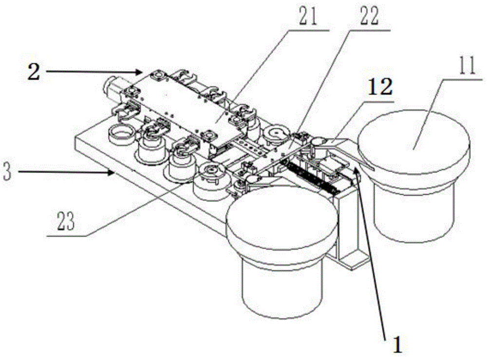
[0058] The system of this embodiment includes a feeding mechanism 1, a multi-station manipulator 2 and a control device. The feeding mechanism 1 is installed at the rear of the multi-station manipulator, and the control device controls the actions of corresponding components;

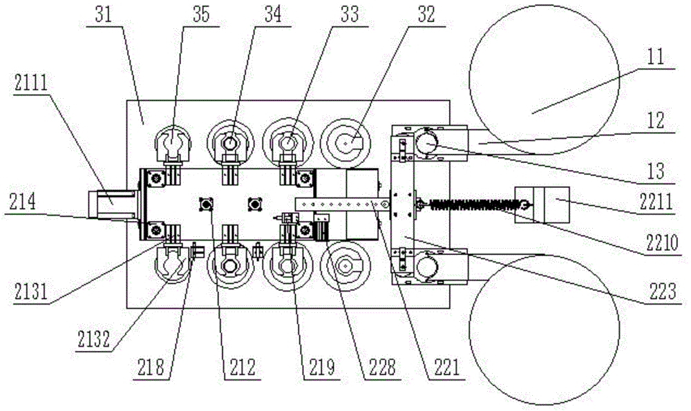
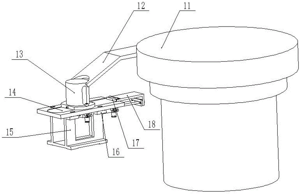
[0059] The feeding mechanism 1 includes a vibrating plate 11, a vibrating plate track 12, a feeding cylinder 13, a feeding track 14, a track support 15, a thin cylinder 16, a push claw 17 and a push claw mounting plate 18, and the vibrating plate 11 and The ends of the vibrating disc track 12 are connected, and the front end of the vibrating disc track 12 is provided with a blanking opening, which is connected to the top of the upper feeding cylinder 13, and the upper feeding cylinder 13 is vertically installed on the feeding rail 14; The material rail 14 is fixedly connected with the lower mold frame 31 through the rail bracket 15, and a thin air cylinder 16 is installed on the bottom of the feeding rai...

Embodiment 2

[0069] This embodiment adopts the above connection relationship, and the difference from Embodiment 1 is that the front end of the vibrating plate track 12 in this embodiment is provided with an arc-shaped blanking opening, through which the arc-shaped blanking opening is connected to the top of the upper barrel 13 .

Embodiment 3

[0071] This embodiment adopts the above-mentioned connection relationship, and the difference from Embodiment 2 is that the number of guiding devices 214 in this embodiment is four, which are respectively installed on the four corners between the middle plate and the top plate, and each guiding device 214 is Including guide sleeve 2141, guide shaft 2142 and bolt 2143, guide shaft 2142 is fixedly installed on the middle plate 216 by bolt 2143, guide sleeve 2141 is sleeved on guide shaft 2142, and guide sleeve 2141 is fixed on the upper surface of top plate 217.


PUM


Abstract

The invention relates to a multi-station material conveying system. The multi-station material conveying system comprises a control device. The multi-station material conveying system is characterized by comprising a feeding mechanism and a multi-station mechanical arm, wherein the feeding mechanism is installed at the rear portion of the multi-station mechanical arm; the feeding mechanism comprises vibrating disks, vibrating disk tracks, feeding cylinders, feeding tracks, track supports, thin cylinders, push jaws and push jaw installation plates, wherein each vibrating disk is connected with the tail end of the corresponding vibrating disk track, blanking ports are formed in the front ends of the vibrating disk tracks, the blanking ports are connected with the top ends of the feeding cylinders, and the feeding cylinders are vertically installed on the feeding tracks; the feeding tracks are fixedly connected with a lower mold frame through the track supports, the thin cylinders are installed at the bottoms of the feeding tracks, and the tail end of a piston rod of each thin cylinder is fixedly connected with the tail end of the corresponding push jaw installation plate; the multi-station mechanical arm comprises a main machine body, a sucking disk device and a protection device, and the protection device is arranged at the periphery of the main machine body.

Description

technical field [0001] The invention relates to the technical field of mechanical handling, in particular to a multi-station material conveying system. The material refers to sheet stamping and forming workpieces. Background technique [0002] The stamping production process is favored by enterprises because of its chip-free forming. Various stamping companies use a large number of punching machines to process and produce products. Traditional processing of stretched products requires a set of molds for each process, which are installed on different punching machines in sequence, and stamping is completed one by one. Each process in this process is mostly completed by manual operation. In the processing process of traditional stretched products, due to the many processes, molds, equipment and operators, the processing of stretched products is complicated, the cost is high, and the processing accuracy is low. And most of the above-mentioned procedures need manual operation...

Claims


Application Information

Patent Timeline
IPC IPC(8): B21D43/05B21D43/11B21D43/18B25J11/00B25J15/08
CPCB21D43/05B21D43/11B21D43/18B25J11/005B25J15/08
Inventor 肖艳军冯华王大源康炎平
Owner HEBEI UNIV OF TECH
Why Eureka
Try Eureka