Petroleum pipeline machining equipment

A technology for oil pipelines and processing equipment, applied in metal processing equipment, shearing machine equipment, pipe cutting devices, etc., can solve the problems of affecting the sealing effect, uneven cutting, low efficiency, etc., to ensure the cutting effect and deepen the cutting thickness. Effect

Inactive Publication Date: 2015-07-22
CHENGDU LAIBAO PETROLEUM EQUIP
View PDF7 Cites 2 Cited by
  • Summary
  • Abstract
  • Description
  • Claims
  • Application Information

AI Technical Summary

Problems solved by technology

[0003] In order to solve defects such as uneven cutting, affecting sealing effect, and low efficiency, the present invention provides an oil pipeline cutting machine

Method used


Image

  • Petroleum pipeline machining equipment
  • Petroleum pipeline machining equipment
  • Petroleum pipeline machining equipment

Examples


Embodiment 1

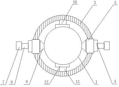
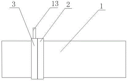
[0018] like figure 1 , figure 2 , Figure 4 As shown, an oil pipeline processing equipment includes a hoop 2 sleeved on an oil pipeline 1, a ring hole 14 is opened on the side of the hoop 2, a cutting ring 3, and a cutting ring fixed on one side of the cutting ring 3 are also included. Ring 3 concentric circular ring 15 and cutter 4 fixed on the other side of cutting ring 3, circular ring 15 is rotatably arranged in circular ring hole 14; Cutter 4 comprises cutting seat 5, cutting knife 6, and cutting seat 5 is The cavity structure with both ends open, the cutting knife 6 slides through the cutting seat 5 and is set in the cutting seat 5; it also includes a hydraulic cylinder 7 fixed on the cutting knife 6, and the piston rod 8 in the hydraulic cylinder 7 is connected to the position where the cutting knife 6 is located. Cut ring 3 on the outer end.

[0019] In this embodiment, let the hoop 2 be firmly sleeved on the oil pipeline 1 first, and the cutting ring 3 is rotated ...

Embodiment 2

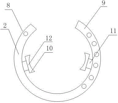
[0021] This embodiment is on the basis of embodiment 1, as image 3 As shown, the hoop 2 includes a steel strip 9, the rear end of the steel strip 9 is a cavity with an open end, the left side of the front end of the steel strip 9 is provided with a threaded counterbore, and the left side of the rear end of the steel strip 9 is evenly opened There is a through hole communicating with the cavity, the front end of the steel strip 9 is inserted into the cavity at the rear end of the steel strip 9 and fixed by a bolt that passes through the through hole and is threadedly connected with the threaded counterbore; the circular hole 14 is arranged on the steel strip 9 to the right of the .

[0022] In this embodiment, the hoop 2 can be firmly fixed on the oil pipeline 1 only by passing the bolts through the holes at both ends of the steel strip 9 at the same time. The other end of the steel belt 9 is provided with even holes on the circumference surface so that the size of the hoop 2...

Embodiment 3

[0024] This embodiment is on the basis of embodiment 1 or embodiment 2, as image 3 As shown, it also includes a deck 10 arranged on the inner surface of the hoop 2; the deck 10 includes a base 11, a draw-in groove 12 fixed on the base 11, the front end of the draw-in slot 12 is an arc structure, and the base 11 is fixed on the embrace on the inner surface of hoop 2.

[0025] In this embodiment, the front end of the clamping groove 12 has an arc-shaped structure, so that the hoop 2 can be sleeved on the oil pipeline 1 more stably.


PUM


Abstract

The invention discloses petroleum pipeline machining equipment. The petroleum pipeline machining equipment comprises a hoop arranged on a petroleum pipeline in a sleeving mode, and a hole is formed in the side face of the hoop. The petroleum pipeline machining equipment further comprises a cutting ring which penetrates through the hole formed in the side face of the hoop and is arranged in the hoop in a rotating mode, and cutters which are fixed on the left side and the right side of the upper surface of the cutting ring respectively. Each cutter comprises a cutting base and a cutter body. Each cutting base is of a cavity structure with the two end faces opened, grooves are formed in the inner walls of cavities of the cutting bases, and the cutter bodies penetrate through openings in the front end face and the rear end face of the corresponding cutting base to be arranged in the grooves in a sliding mode. The petroleum pipeline machining equipment further comprises hydraulic cylinders fixed on the cutter bodies, and piston rods in the hydraulic cylinders are connected to the ends, located outside the cutting ring, of the cutter bodies. According to the petroleum pipeline machining equipment, the position of the cutting ring is made unchanged through the hoop, and it is guaranteed that the cutter bodies can cut the petroleum pipeline smoothly due to the arrangement of the hoop; the hydraulic cylinders fixed at the ends of the cutter bodies can continuously push the cutter bodies to move in the to-be-cut direction of the petroleum pipeline, the cutting thickness is increased continuously, and the cutting effect is guaranteed.

Description

technical field [0001] The invention relates to cutting equipment, in particular to an oil pipeline processing equipment. Background technique [0002] In the oil industry, it is necessary to lay long pipelines for oil transportation, but because most of the oil pipelines are laid in relatively harsh environments, leakage and rupture often occur. If the damage is too large, repair welding cannot be done. , it is necessary to cut off the damaged part and replace it with a new pipe. During the replacement process, it is necessary to ensure that the cut pipe is flat. But existing operation is generally surrounded the outer wall of oil pipeline by a people with circle band, and another people draws a line along circle band with special stone pen, then cuts along the line drawn. The problem with this method is that when the diameter of the pipe is large, two people must operate at the same time to complete the work of drawing the line, which is a waste of manpower, and cutting ...

Claims


Application Information

Patent Timeline
Patent Type & Authority Applications(China)
IPC IPC(8): B23D21/04B23D21/10
Inventor 谭正怀
Owner CHENGDU LAIBAO PETROLEUM EQUIP
Why Eureka
Try Eureka