Electricity generation device

A technology for power generation devices and generators, which is applied in the fields of ocean energy power generation, engine components, machines/engines, etc., can solve the problems of inability to popularize and apply, high maintenance costs, and poor investment benefits, and achieves good environmental adaptation, easy construction, and resistance to good wind effect

Inactive Publication Date: 2015-07-22
陈建希
View PDF6 Cites 2 Cited by
  • Summary
  • Abstract
  • Description
  • Claims
  • Application Information

AI Technical Summary

Problems solved by technology

[0002] At present, our country has a long coastline and a vast sea area, and there are thousands of islands in the offshore, such as: Zhoushan Islands, Taiwan Island, Hainan Island, South China Sea Islands, Wanshan Island, etc., the power supply required for coastal areas and islands , fresh water and other resources cannot be popularized to obtain energy from sea surges and tides. The current solution relies on building thermal power plants to generate electricity, wind power, solar photovoltaic power generation, or long-distance ultra-high voltage power grid power supply. To build a large-scale tidal power generation, the diameter of the turbine is up to 100 meters, the investment is billions of dollars, the power generation capacity is tens of watts, and the tidal drop power generation is also built. These technical measures have poor investment returns and high maintenance costs, so they cannot be popularized and applied.
If the island is powered by a shore-based power grid, it is necessary to build a submarine high-voltage power supply cable. The investment is also huge and the safety is poor.

Method used


Image

  • Electricity generation device
  • Electricity generation device
  • Electricity generation device

Examples


Embodiment 1

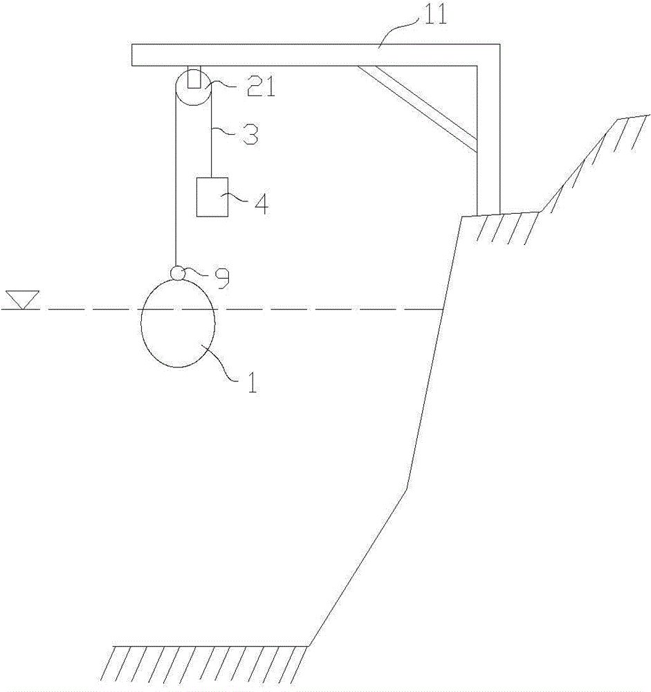
[0031] refer to figure 1 , Figure 6 and Figure 8 , the present embodiment provides a power generating device, comprising a floating cabin 1, an upper fixed-slip ratchet 21, an upper cable 3 and a gravity hammer 4, the position of the upper fixed-slip ratchet 21 is higher than that of the floating cabin 1 and the gravity hammer 4, and the upper fixed-slip ratchet 21 is installed on the bottom of the reinforced concrete beam 11, one end of the upper cable 3 is connected to the upper ring 9 on the upper end of the floating cabin 1, and the other end of the upper cable 3 is connected to the gravity hammer 4 by going around the upper fixed sliding ratchet 21, and the floating cabin 1 is placed on the water surface. The quality of cabin 1 is greater than the quality of gravity hammer 4, and the gravity of floating cabin 1, floating cabin 1 are subjected to the buoyancy of water and the gravity of gravity hammer 4 are in balance.

[0032] The upper fixed-slip ratchet 21 is connec...

Embodiment 2

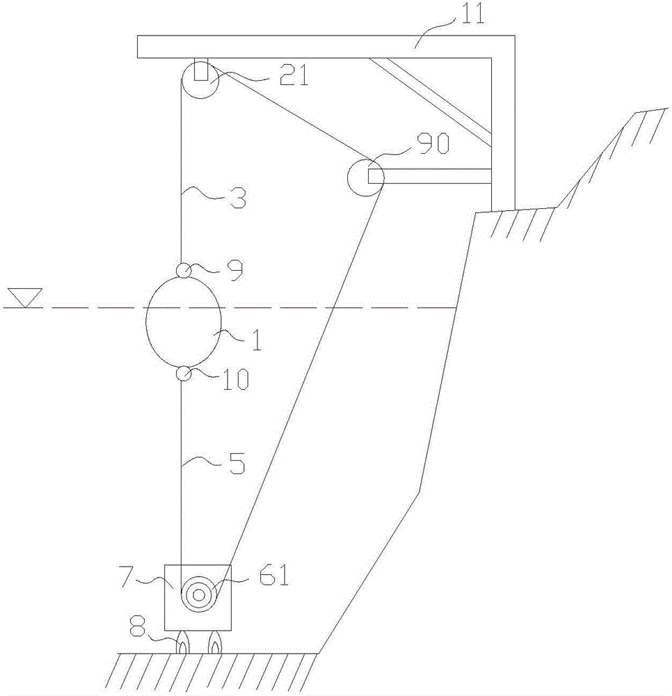
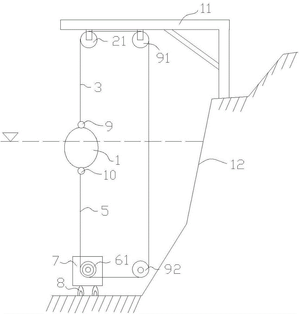
[0035] refer to figure 2 , image 3 , Figure 6 to Figure 8, the present embodiment provides a power generating device, comprising a floating cabin 1, an upper fixed-slip ratchet 21, an upper cable 3, a lower cable 5, a lower fixed-slip ratchet 61, and the upper fixed-slip ratchet 21 is installed at the bottom of a reinforced concrete beam 11, and the upper fixed-slip ratchet The position of the ratchet 21 is higher than the floating cabin 1, the floating cabin 1 is placed on the water surface, the position of the lower fixed sliding ratchet 61 is lower than the floating cabin 1, the lower fixed sliding ratchet 61 is installed in the fixed housing 7, and the fixed housing 7 passes through the anchor 8 is positioned under the water surface, and the reinforced concrete beam 11 can be arranged on the land-based shore-sea reef 12. At this time, the fixed shell 7 is positioned on the reef under the water surface through the anchor 8; one end of the upper cable 3 is connected to t...

Embodiment 3

[0041] refer to Figure 4 , the present embodiment provides a power generation device, including a floating cabin 1, the floating cabin 1 is placed on the water surface, and also includes a bar-shaped permanent magnet 31, the bar-shaped permanent magnet 31 is installed at the bottom of the reinforced concrete beam 11, and the floating cabin 1 is provided with The first coil 32, the first coil 32 is inserted into the bar-shaped permanent magnet 31, that is, the bar-shaped permanent magnet 31 passes through the first coil 32, the floating cabin 1 rises or falls with the change of the water surface height, and the first coil 32 moves along the The bar-shaped permanent magnet 31 moves up and down, thereby generating an electromotive force, and the electric energy is output through the output end of the first coil 32 .


PUM


Abstract

The invention provides an electricity generation device which comprises a floating cabin, an upper fixed sliding ratchet wheel, an upper mooring rope and a gravity hammer. The upper fixed sliding ratchet wheel is higher than the floating cabin and the gravity hammer. One end of the upper mooring rope is connected with the upper end of the floating cabin. The other end of the upper mooring rope winds around the upper fixed sliding ratchet wheel to be connected with the gravity hammer. The floating cabin is arranged on the water surface. The mass of the floating cabin is larger than that of the gravity hammer. The upper fixed sliding ratchet wheel is connected with a first electricity generator through a first acceleration transformer, and an output shaft of the first acceleration transformer is coaxial with a rotor shaft of the first electricity generator. The electricity generation device has the advantages of being low in investment, easy to build, good in wind resistance, good in environmental adaptability, high in economic benefit, long in service life and capable of meeting electricity consumption requirement to the highest possible, being the optimal technology for converting wave energy into electric energy, and being the green and environment-friendly new energy renewing technology.

Description

technical field [0001] The invention relates to the field of sea surge power generation, in particular to a power generation device. Background technique [0002] At present, our country has a long coastline and a vast sea area, and there are thousands of islands in the offshore, such as: Zhoushan Islands, Taiwan Island, Hainan Island, South China Sea Islands, Wanshan Island, etc., the power supply required for coastal areas and islands , fresh water and other resources cannot be popularized to obtain energy from sea surges and tides. The current solution relies on building thermal power plants to generate electricity, wind power, solar photovoltaic power generation, or long-distance ultra-high voltage power grid power supply. To build a large-scale tidal power generation, the diameter of the turbine is up to 100 meters, the investment is billions of dollars, the power generation capacity is tens of watts, and the tidal drop power generation is also built. These technical me...

Claims


Application Information

Patent Timeline
Patent Type & Authority Applications(China)
IPC IPC(8): F03B13/14
CPCY02E10/30
Inventor 陈建希
Owner 陈建希
Why Eureka
Try Eureka