Indoor simulation method for space target optical characteristic actual measurement conditions

A technology for space targets and optical characteristics, applied in the field of optical characteristics measurement of space targets, can solve the problems of low-precision analog measurement of optical characteristics of small-sized space debris, insufficient center point stability, large circular experimental space, etc., to facilitate automatic operation. , The effect of low center point stability and low angle control accuracy

Inactive Publication Date: 2015-07-22
ACAD OF OPTO ELECTRONICS CHINESE ACAD OF SCI +1
View PDF4 Cites 14 Cited by
  • Summary
  • Abstract
  • Description
  • Claims
  • Application Information

AI Technical Summary

Problems solved by technology

[0008] However, there are shortcomings in this scheme: in order to realize the 360-degree rotation of the spiral arm, this scheme requires a large circular experimental space, and a dedicated large-area laboratory needs to be established.
Although the central manipulator can realize the three-axis attitude control of the target, its load-bearing capacity is small, the attitude angle accuracy is low, and the stability of the center point is insufficient.
In addition, for the measurement of large-scale targets, it is necessary to use a large-caliber solar simulation light source, which is too large to be installed and used on the spiral arm, so this solution is still only suitable for low-precision analog measurement of the optical properties of small-sized space debris

Method used


Image

  • Indoor simulation method for space target optical characteristic actual measurement conditions
  • Indoor simulation method for space target optical characteristic actual measurement conditions
  • Indoor simulation method for space target optical characteristic actual measurement conditions

Examples


Embodiment Construction

[0061] The indoor simulation method of the actual measurement conditions of the optical characteristics of the space object of the present invention comprises:

[0062] Step 1, arrange the device for the actual measurement conditions of the optical characteristics of the space target:

[0063] Such as Figure 4 and Figure 5 As shown, the device for measuring the optical characteristics of the space object of the present invention includes a light source 1, a mirror 2, a three-axis turntable 3, a detector 4, a detector guide rail 5, a space object model 6 and a detector support 7; the specific design is as follows

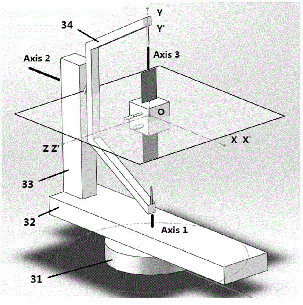
[0064] Select a semicircle area indoors, and install a three-axis turntable 3 at the center of the semicircle area;

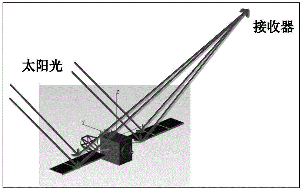
[0065] A light source 1 and a reflector 2 are installed outside the semicircular area, and the light emitted by the light source 1 is reflected by the reflector 2 to the space object model 6 installed on the three-axis turntable 3;

[0066] Detec...


PUM


Abstract

The invention provides an indoor simulation method for space target optical characteristic actual measurement conditions. The indoor simulation method for the space target optical characteristic actual measurement conditions comprises the following steps of step 1, arranging a simulation device for the space target optical characteristic actual measurement conditions; step 2, establishing a body coordinate system for a space target model; step 3, establishing a reference coordinate system for an indoor simulation device; step 4, defining a light source vector VL and a detector vector VD; step 5, establishing an auxiliary coordinate system; step 6, enabling three axes of the body coordinate system and three axes of the reference coordinate system to be coincided respectively and the detector vector VD and the light source vector VL to be parallel at the zero moment; step 7, obtaining angular variation on a real satellite from the moment t to the zero moment after the illumination and detection angles of the real satellite are changed at some moment t, adjusting the indoor simulation system according to the above three coordinate systems and achieving simulation of real space target illumination and observation conditions to further achieve simulation of a real space target observation process.

Description

technical field [0001] The invention belongs to the field of optical characteristic measurement of space objects, in particular to an indoor simulation method for actual measurement conditions of optical characteristics of space objects. Background technique [0002] The indoor simulation technology of the optical characteristics of space targets uses equipment and methods to simulate the space lighting conditions faced by space targets in the laboratory, and at the same time simulates the relative geometric relationship between the light source-target-detector. The purpose is to realize the actual observation process (ground-based telescope observation , space-based payload observations) and parallel simulation of observation data. Using laboratory simulation, it can assist in the establishment of various theoretical models of the target optical properties, and can compare the actual observation data to study the influence of various factors such as target shape, phase angl...

Claims


Application Information

Patent Timeline
IPC IPC(8): G01D11/00
Inventor 赵飞徐融杨新项磊
Owner ACAD OF OPTO ELECTRONICS CHINESE ACAD OF SCI
Why Eureka
Try Eureka