
Spectrum testing system using tunable laser light source

A spectrum testing and laser light source technology, applied in the field of optical communication, can solve the problems of slow testing rate, insufficient sensitivity, high cost, etc., and achieve the effect of simple structure, high sensitivity and cost saving.

Active Publication Date: 2015-07-22
GUANGXUN SCI & TECH WUHAN
View PDF6 Cites 2 Cited by
  • Summary
  • Abstract
  • Description
  • Claims
  • Application Information

AI Technical Summary

Problems solved by technology

[0005] The technical problem to be solved by the present invention is to provide a new test scheme for the shortcomings of existing spectrum analyzers such as low resolution, slow test rate, insufficient sensitivity, and high cost when testing passive optoelectronic devices. A low-cost way to realize simultaneous high-sensitivity and rapid testing of the spectral properties of multiple passive optoelectronic devices in a certain wavelength range

Method used


Image

  • Spectrum testing system using tunable laser light source
  • Spectrum testing system using tunable laser light source
  • Spectrum testing system using tunable laser light source

Examples


Embodiment Construction

[0043] In order to make it easier for those skilled in the art to understand and implement the present invention, the present invention will be further described in detail below in conjunction with the accompanying drawings and specific embodiments.

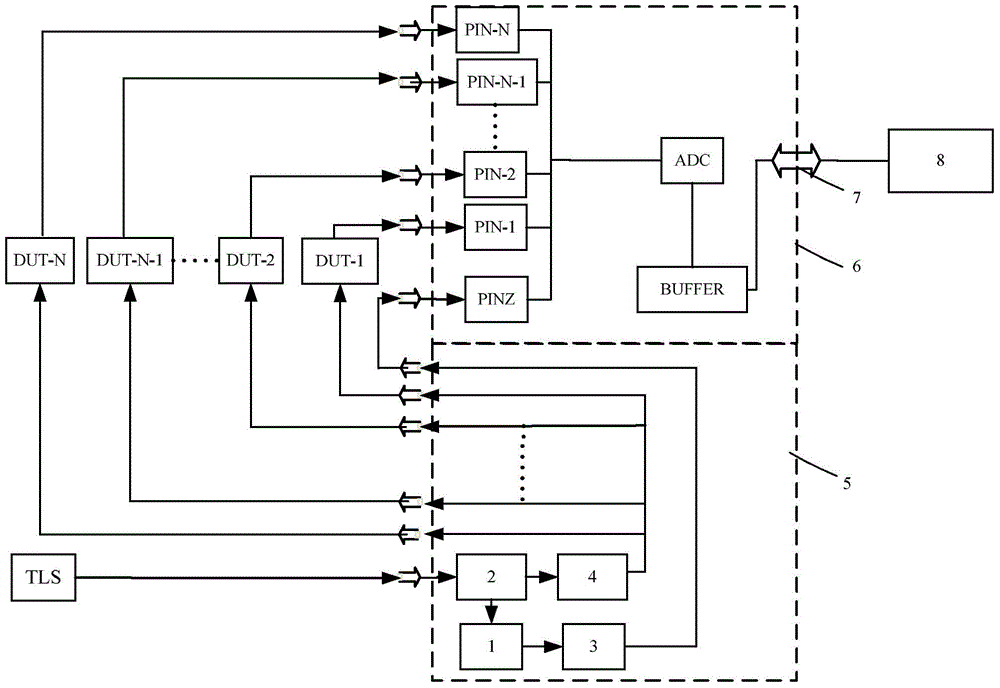
[0044] figure 1It is a schematic diagram of the overall structure of the spectral characteristic testing system of the present invention. The spectral characteristic testing system includes an optical path part 5, a hardware part 6, a tunable laser source TLS and a host computer, and the output terminal of the tunable laser light source TLS and the 1× 2 The input end of the power coupler 2 is connected, and the optical signal output by the TLS is divided into a test light and a reference light. The TLS is a narrow-band, high-isolation, high-speed, tunable laser source that scans cyclically within a certain wavelength range, and can be used to replace the diffraction grating, a light splitting element in a traditional optical spec...


PUM


Abstract

The invention relates to a spectrum testing system using a tunable laser light source. The spectrum testing system comprises the tunable laser light source, a light path part, a hardware part and an upper computer. An optical synchronization device composed of a band-pass filter and an etalon is arranged on the light path part. The tunable laser source is divided into two paths after power distribution is conducted through a 1*2 power coupler, wherein one path is used for synchronization, and the other path is connected with to-be-tested passive photoelectronic devices in all testing channels through a 1*N power coupler. Sampling circuits collect response signals of synchronization channels and the photoelectronic devices in all the testing channels in parallel, and send the response signals to the upper computer through a network to be processed. A server / client side framework is adopted for the upper computer. A server side program is responsible for synchronizing sampled data of all the channels, and a client side program is responsible for restoring true spectrum data of the to-be-tested passive photoelectronic devices in the first channel, the second channel...the Nth channel. By means of the spectrum testing system, multiple channels can conduct multi-channel spectrum analysis through one TLS light source in a multiplexing mode, and the system cost is reduced to an extremely large extent.

Description

technical field [0001] The invention relates to a system for testing the spectrum characteristics of passive optoelectronic devices, in particular to a TLS+PD spectrum testing system, which belongs to the field of optical communication. Background technique [0002] Passive optoelectronic devices are an important part of optical fiber communication systems. Under the trend of optical fiber communication networks developing towards large capacity and high speed, passive optoelectronic devices are particularly important. In recent years, new materials, new processes, and new products are constantly emerging, and passive optoelectronic devices are ushering in a period of rapid development. With the increase in demand, how to use a low-cost, high-precision It is particularly important to quickly test the spectral characteristics of passive optoelectronic devices in a fast way. [0003] The common test method for the spectral characteristics of existing passive optoelectronic de...

Claims


Application Information

Patent Timeline
Patent Type & Authority Applications(China)
IPC IPC(8): G01M11/02
Inventor 杨波宋琼辉何俊柳刚谢卉陈建宇周园
Owner GUANGXUN SCI & TECH WUHAN
Learn More