
Method for remedying halohydrocarbon contaminated site through combination of chemical leaching and microorganisms

A chemical rinsing and microbial technology, applied in the field of restoration of halocarbon-contaminated sites, can solve problems such as difficulty in ensuring the accurate arrival of chemical reagents, microbial toxicity, and short residence time of chemical reagents, and achieve complete restoration of halocarbon pollutants , the effect of complete repair

Active Publication Date: 2015-07-29
山东冽泉环保工程咨询有限公司
View PDF7 Cites 11 Cited by
  • Summary
  • Abstract
  • Description
  • Claims
  • Application Information

AI Technical Summary

Problems solved by technology

[0003] For the remediation of halogenated hydrocarbon-contaminated sites, the main technologies include bioremediation technology, chemical oxidation / reduction technology, improved gas phase extraction technology, chemical leaching technology, etc., but these technologies are more or less deficient, such as bioremediation technology Usually, due to the high concentration of halogenated hydrocarbon pollutants, the microorganisms are poisoned, thereby weakening the effect of bioremediation; while the chemical oxidation / reduction technology is difficult to ensure that the injected chemical reagents reach the pollution sources in the aquifer accurately. Usually, the residence time in the pollution source area is short, which cannot meet the needs of sufficient oxidation / reduction of pollutants; during the chemical leaching process, the chemical leaching agent will form a preferential flow path in the underground aquifer after being injected into the underground aquifer, resulting in low The pollutants in the permeable local area cannot be leached out, and the concentration of pollutants will rebound after leaching, which will finally affect the leaching effect
In addition, chemical leaching is not effective for low-concentration pollutants

Method used


Image

  • Method for remedying halohydrocarbon contaminated site through combination of chemical leaching and microorganisms

Examples


Embodiment Construction

[0012] 1) Choose rhamnose as the biosurfactant in the prepared eluent, and choose glycerol as the alcohol in the eluent, in which rhamnose, glycerol and water account for the proportion of the whole eluent mass 25%, 25% and 50% respectively;

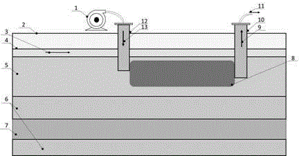
[0013] 2) The site survey found that the selected target polluted sites mainly contain chlorinated hydrocarbon DNAPLs, the pollution source area 8 containing DNAPLs is 4-7 meters underground, the groundwater level line 4 is 2.5 meters underground, and the groundwater flow direction 3 is from west to east direction, the hydrogeology of the contaminated site mainly includes an unsaturated layer 0.8 meters thick below the groundwater level, a free aquifer 5 with a depth of 3.3 meters to 8 meters above the ground, an isolation layer 6 under the free aquifer, and an isolation layer under the isolation layer. Confined aquifer 7, there is another layer of isolation layer under the confined aquifer 7, such as figure 1 shown;

[0014] 3) The me...


PUM


Abstract

The invention relates to a method for remedying a halohydrocarbon contaminated site through combination of chemical leaching and microorganisms, in particular to a leaching method and a microorganism remediation method. The method for remedying the halohydrocarbon contaminated site comprises steps as follows: chemical leaching is adopted, leachate is injected into contaminated soil through an injection well, and the leachate with pollutants is pumped out from an extraction well at the downstream part of the contaminated site. The method is characterized in that the major component of the leachate is a biological surfactant dissolved in an alcohol-water mixed solution, and after the contaminated site is leached by the leachate, a KB1 bacteria suspension is injected into the contaminated soil for microorganism remediation. Due to leaching with the chemical method, the early-stage remediation for the high-concentration halohydrocarbon contaminated site can be realized quickly, then with the adoption of microorganism remediation, the problems that the low-concentration pollutant leaching effect of the chemical leaching technology is poor and the concentration of pollutants is rebounded after leaching can be solved, and the purpose of complete remediation of the halohydrocarbon pollutants is achieved.

Description

technical field [0001] The invention relates to a restoration method for halogenated hydrocarbon-contaminated sites, in particular to a washing method and a microbial restoration method. Background technique [0002] The increasingly serious soil pollution has caused great harm to food security and ecological security. Numerous substances that cause soil pollution include heavy metals, organic pollutants, pesticides, herbicides, POPs, and fertilizers. These pollutants are not only deposited and enriched on the soil surface, but also diffuse into the aquifer below the soil layer, thereby contaminating groundwater and causing greater health risks. Among various pollutants, halogenated organic compounds are more likely to deposit into underground aquifers to form a substance called heavy non-aqueous phase liquid (dense non-aqueous phase liquid) due to their specific characteristics such as higher density than water and low solubility in water. -aqueous phase liquids, DNAPLs),...

Claims


Application Information

Patent Timeline
IPC IPC(8): B09C1/02B09C1/08B09C1/10
Inventor 刘骁勇李静
Owner 山东冽泉环保工程咨询有限公司
Learn More