High-orbit optical remote sensor vacuum hot test external heat flow simulation method

An optical remote sensor and vacuum thermal test technology, which is used in simulation devices for space navigation conditions, space navigation equipment, transportation and packaging, etc. Engineering Realizability, Improve Heat Flow Simulation Accuracy, Reduce the Effect of Rotation Amplitude

Active Publication Date: 2015-07-29
BEIJING RES INST OF SPATIAL MECHANICAL & ELECTRICAL TECH
View PDF4 Cites 12 Cited by
  • Summary
  • Abstract
  • Description
  • Claims
  • Application Information

AI Technical Summary

Problems solved by technology

[0006] The technical problem solved by the invention is to solve the problem that the existing non-contact space optical remote sensor external heat flow simulation method does not have the characteristics and directionality of the solar spectrum energy spectrum, and provides a vac

Method used


Image

  • High-orbit optical remote sensor vacuum hot test external heat flow simulation method
  • High-orbit optical remote sensor vacuum hot test external heat flow simulation method
  • High-orbit optical remote sensor vacuum hot test external heat flow simulation method

Examples


Embodiment Construction

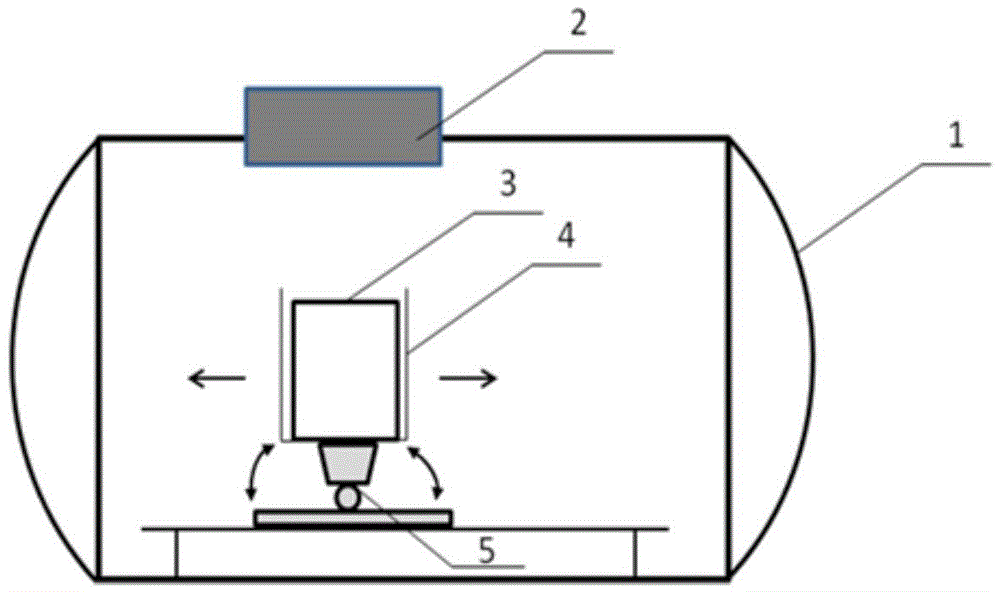
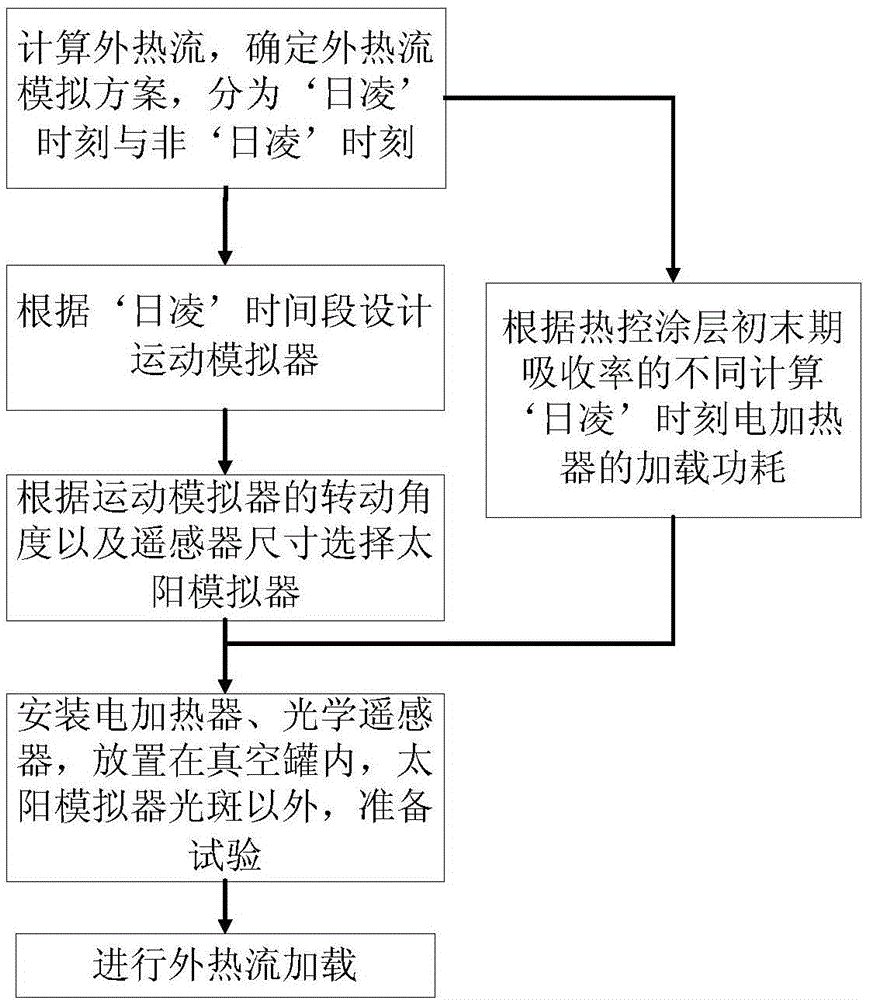
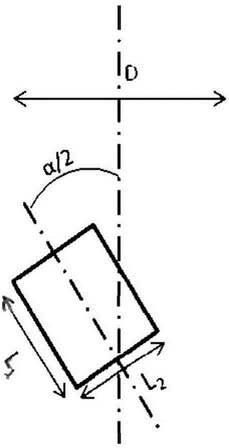
[0024] The optical system of the high-orbit space remote sensor may face a long-term "sun transit" phenomenon in orbit. The contact external heat flow simulation method will destroy the surface structure of the optical system, which cannot be applied in the identification and normal ground thermal test. simulator. However, if a solar simulator is used for the entire track, and considering the relative position changes between the sunlight and the remote sensor, there are high requirements for the spot size of the solar simulator, the space of the vacuum simulation system, and the ability of the motion mechanism. Determine the external heat flow simulation scheme according to the external heat flow received by the remote sensor.

[0025]In the present invention, the optical remote sensor is divided into two parts for consideration, one part is the optical system that must adopt the non-contact external heat flow simulation scheme, and the other part is the shading cover and the...


PUM


Abstract

A high-orbit optical remote sensor vacuum hot test external heat flow simulation method comprises the steps of firstly determining solar radiation heat flow according to on-orbit solar absorptance of an optical remote sensor (3), secondarily arranging the optical remote sensor (3) in a vacuum environment simulation chamber (1), then determining a 'sun outage' time period by judging whether the solar radiation heat flow Q1 (t) absorbed by an optical system within a orbit period is 0 or not, determining the time period of the Q1 (t) unequal to 0 as the 'sun outage' time period, adopting a solar simulator (2) and electric heater combined simulation scheme to perform outer heat flow simulation, determining that the time period of the Q1 (t) equal to 0 is a 'non-sun outage' time period, and adopting an independent electric heater simulation scheme to perform outer heat flow simulation. The problem that an existing non-contact space optical remote sensor outer heat flow simulation method does not have a solar spectral energy spectrum characteristic and directionality is solved, energy distribution of solar spectrum of the remote sensor on orbit can be accurately simulated, simulation accuracy is high, and project realization is promoted.

Description

technical field [0001] The invention belongs to the field of thermal control, and relates to an environmental thermal test method of an aerospace optical remote sensor. Background technique [0002] Space optical remote sensors have to endure the alternating heating and cooling of the sun, planets, and space low-temperature heat sinks for a long time during their orbital operation. The working environment is extremely harsh, and the surface of the remote sensor faces drastic temperature changes. With the increasing demand for optical resolution, extremely high requirements are placed on the operating temperature of the optical-mechanical system. Therefore, it is necessary to adopt reasonable and effective thermal control technology to achieve precise temperature control of the remote sensor. [0003] In order to verify the rationality of the thermal control scheme and the temperature control ability of thermal control products, sufficient ground environmental tests are requi...

Claims


Application Information

Patent Timeline
IPC IPC(8): B64G7/00
Inventor 于峰徐娜娜李春林赵宇赵振明颜吟雪刘伏龙郭楠高长春
Owner BEIJING RES INST OF SPATIAL MECHANICAL & ELECTRICAL TECH
Why Eureka
Try Eureka