

Rapid dehydration device for mud with high water content
A rapid dehydration and slurry technology, applied in the direction of dehydration/drying/thickened sludge treatment, etc., can solve the problems of shortened equipment life, easy blockage of slag outlet, high energy consumption, etc., and achieve increased discharge efficiency, good dehydration effect, and high energy consumption. The effect of low consumption
- Summary
- Abstract
- Description
- Claims
- Application Information
AI Technical Summary
Problems solved by technology
Method used
Image

Examples
Embodiment 1
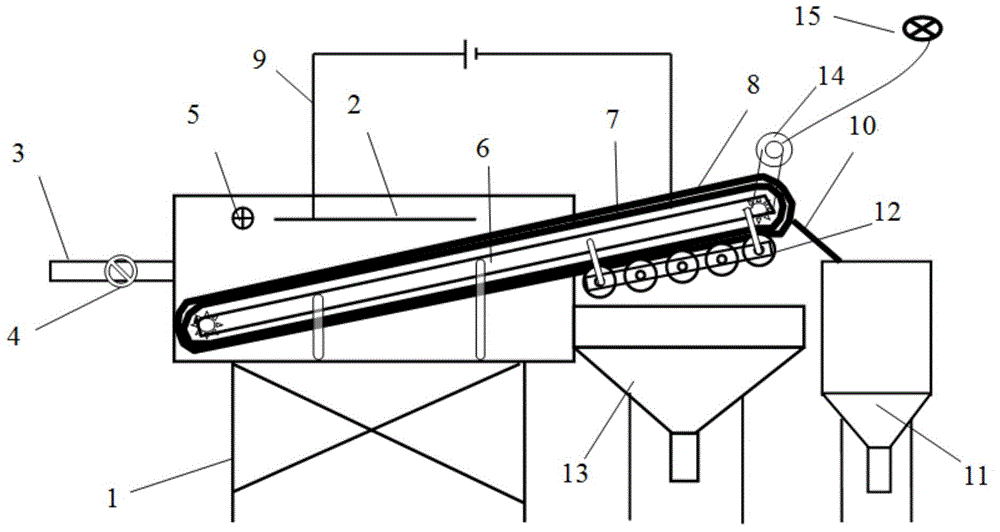
[0045] For the effect of the mud dehydration example with a water content of 150%. Such as figure 1As shown, the present embodiment provides a rapid dehydration device for high cement slurry, which consists of a support 1, a mud tank 2, a mud inlet pipe 3, an electric valve 4, a liquid level sensor 5, a conveyor belt bracket 6, a conveyor belt 7, Water-absorbing belt 8, electroosmosis component 9, mud scraper 10, mud receiving tank 11, dehydration roller 12, water receiving tank 13, low-speed motor 14, AC power supply 15, wherein:
[0046] The mud tank 2 is installed on the bracket 1; the mud inlet pipe 3 is connected to the left side wall of the mud tank 2; Connect; Conveyor belt support 6 becomes 30 ° and is arranged in muddy water tank 2, and its one end stretches out muddy water tank 2 from the opening on muddy water tank 2 right sides; The metal conveyor blocks are connected by hinges; the water-absorbing belt 8 is set on the conveyor belt 7 and moves with the conveyor ...
Embodiment 2
[0070] For the effect of the mud dehydration example with a water content of 180%. Such as figure 1 As shown, this embodiment provides a system device with XX quick mud dehydration function, which consists of a bracket 1, a mud tank 2, a mud inlet pipe 3, an electric valve 4, a liquid level sensor 5, a conveyor belt bracket 6, a conveyor belt 7, Water-absorbing belt 8, electroosmosis component 9, mud scraper 10, mud receiving tank 11, dehydration roller 12, water receiving tank 13, low-speed motor 14, AC power supply 15, wherein:
[0071] The mud tank 2 is installed on the bracket 1; the mud inlet pipe 3 is connected to the left side wall of the mud tank 2; Connection; the conveyor belt support 6 is set in the mud tank 2 at 25°, and one end of it stretches out of the mud tank 2 from the opening on the right side of the mud tank 2; On the bracket 6, the metal conveying blocks are connected by hinges; the low-speed motor 14 is installed on the upper end of the conveyor belt br...
PUM
| Property | Measurement | Unit |
|---|---|---|
| Size | aaaaa | aaaaa |
| Size | aaaaa | aaaaa |
Abstract
Description
Claims
Application Information