Resonance enhanced type broadband impedance matching circuit and matching method

An impedance matching and enhanced technology, applied in impedance networks, electrical components, multi-terminal pair networks, etc., can solve the problems of narrow frequency bandwidth and inability to use broadband impedance matching, and achieve the effect of broadband impedance matching.

Active Publication Date: 2015-07-29
NO 54 INST OF CHINA ELECTRONICS SCI & TECH GRP
View PDF4 Cites 8 Cited by
  • Summary
  • Abstract
  • Description
  • Claims
  • Application Information

AI Technical Summary

Problems solved by technology

The lumped parameter compensation technology uses lumped resistors, capacitors, and inductors to achieve impedance matching. This method has a simple structure and good matching performance at low frequencies. However, due to the limitations of the components used, additional parasitic parameters will be introduced in high-frequency applications.
Distributed parameter compensation technology uses microstrip lines of specific length and width to realize the series-parallel effect of equivalent capacitance and inductance. This method can be applied to higher frequencies, but its disadvantage is that the frequency bandwidth is narrow and cannot be used at low frequencies. Wideband Impedance Matching Near DC

Method used


Image

  • Resonance enhanced type broadband impedance matching circuit and matching method
  • Resonance enhanced type broadband impedance matching circuit and matching method
  • Resonance enhanced type broadband impedance matching circuit and matching method

Examples


Embodiment 1

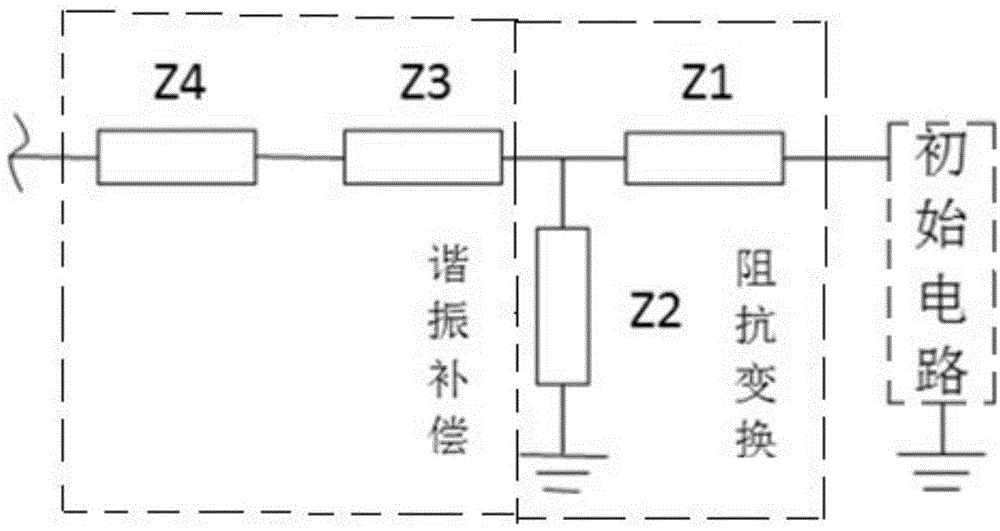
[0029] Such as figure 1 As shown, a resonance-enhanced broadband impedance matching electrical matching circuit: it is composed of an impedance transformation network and a resonance compensation network cascaded with the initial circuit in sequence; the impedance transformation network is composed of parallel resistors Z1 and impedance Z2; the resonance The compensation network consists of series impedance Z3-Z4. The impedances Z1, Z3-Z4 are implemented with microstrip lines. The parameters of the impedance transformation network are determined by the matching conditions of the low-frequency end of the initial circuit; the parameters of the resonance compensation network are determined by the matching conditions of the high-frequency end of the initial circuit.

Embodiment 2

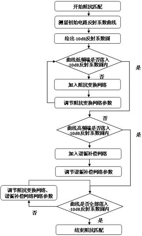
[0031] Such as figure 2 As shown, a matching method of a resonance-enhanced broadband impedance matching circuit includes the following steps:

[0032] A resonance-enhanced broadband impedance matching electrical matching circuit is characterized in that: it is composed of an impedance transformation network and a resonant compensation network cascaded with the initial circuit in sequence; the impedance transformation network is composed of parallel resistors Z1 and impedance Z2; the The resonant compensation network is composed of series connected impedances Z3-Z4; said impedances Z1, Z3-Z4 are implemented with microstrip lines.

[0033] 2. The matching method for the resonance-enhanced broadband impedance matching circuit according to claim 1, characterized in that: comprising the following steps:

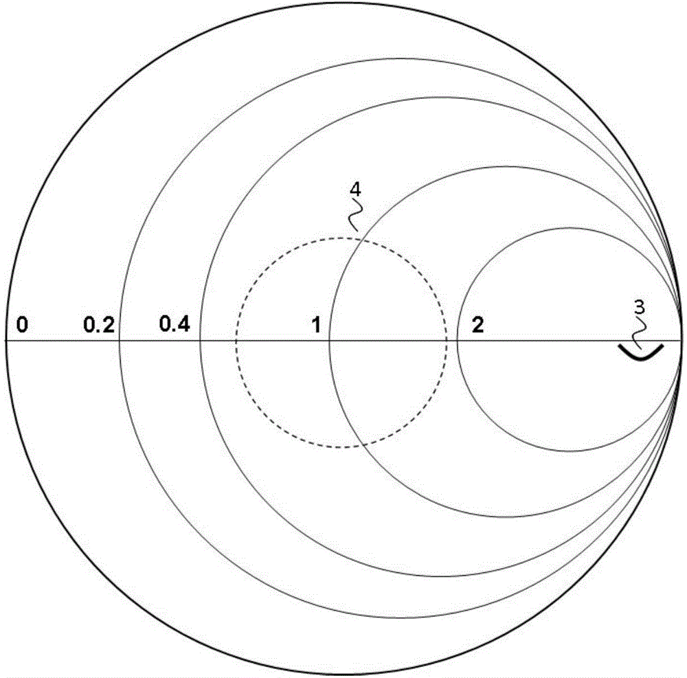
[0034] Step 1: Draw the reflection curve: measure the scattering parameter of the initial circuit, calculate its reflection coefficient, draw the reflection curve 3 of the init...


PUM


Abstract

The invention discloses a resonance enhanced type broadband impedance matching circuit and a matching method. The matching circuit comprises an impedance transformation network and a resonance compensating network which are in cascade connection with an initial circuit in sequence, wherein the impedance transformation network comprises a resistor Z1 and an impedance Z2 which are connected in parallel; the resonance compensating network comprises impedance Z3 to Z4 which are connected in series. The impedances Z1, Z3 to Z4 are realized by a microstrip line. Parameters of the impedance transformation network are determined by low frequency end matching conditions of the initial circuit; the parameters of the resonance compensating network are determined by high frequency end matching conditions of the initial circuit. The matching method comprises the following steps: firstly, accessing the impedance transformation network and regulating the parameters of the impedance transformation network to realize low frequency end matching; then, accessing the resonance compensating network and regulating the parameters of the resonance compensating network to realize high frequency end matching. According to the resonance enhanced type broadband impedance matching circuit and the matching method, the defects in a conventional compensation technology purely using lumped parameter or distribution parameters are compensated, the matching circuit under required frequency band width is conveniently realized, and the broadband impedance matching is realized.

Description

technical field [0001] The invention relates to a broadband impedance matching circuit and a matching method, in particular to a resonance enhanced broadband impedance matching circuit and a matching method, belonging to the technical field of electronic engineering. Background technique [0002] At present, the bandwidth of optical fiber communication network has broken through the 10THz mark under the application of technologies such as wavelength division multiplexing and orthogonal frequency division multiplexing. Most of them are below 10Gbps, which shows that in the existing communication system, the transmitting and receiving terminals of the signal largely limit the bandwidth of the transmission system. [0003] The intrinsic parameter characteristics of the functional chip in the optical network terminal determine the upper limit of the bandwidth of the device. At the same time, the high-frequency packaging of the device will also introduce additional parasitic para...

Claims


Application Information

Patent Timeline
Patent Type & Authority Applications(China)
IPC IPC(8): H03H7/38
Inventor 韩威张书敬余承伟梁栋宁晋哲张静
Owner NO 54 INST OF CHINA ELECTRONICS SCI & TECH GRP
Why Eureka
Try Eureka