
Optical film

A technology of optical film and polarizing layer, applied in the field of optical film, can solve the problems of picture brightness deterioration and invisible images, etc.

Active Publication Date: 2015-07-29
LG CHEM LTD
View PDF5 Cites 4 Cited by
  • Summary
  • Abstract
  • Description
  • Claims
  • Application Information

AI Technical Summary

Problems solved by technology

For example, when viewing such a display device with polarized sunglasses, depending on the relationship between the polarizing layer in the device and the polarization axis of the polarized sunglasses, the brightness of the picture seen by the viewer may be degraded, or in some cases may will not see the image

Method used

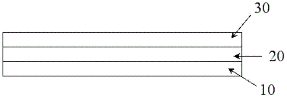
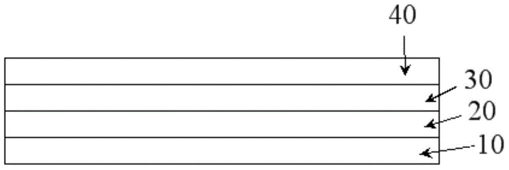

Image

  • Optical film
  • Optical film
  • Optical film

Examples


Embodiment 1 to 4 and comparative Embodiment 1 to 4

[0139] By dissolving 20 g of 5-norbornenyl-2-methyl-(4-methoxycinnamate) as a photoreactive polymer in 980 g of cyclopentanone, 20 g of dipentaerythritol hexaacrylate and as a photoinitiator 5g Irgacure OXE02 (Ciba-Geigy company, Switzerland) to prepare the coating solution for forming the alignment layer, the coating solution is coated on the triacetyl cellulose (TAC) film so that it has about thickness, and dried in a 70°C drying oven for 2 minutes with hot air, thereby forming a layer. Next, the TAC film having the layer was conveyed in one direction, and while using a high-pressure mercury lamp (80 w / cm) as a light source, and a wire grid polarizing plate (Moxtek Corporation) to irradiate the film with linearly polarized ultraviolet rays Exposure was performed once at a rate of 3 m / min, whereby alignment characteristics were obtained.

[0140] Subsequently, a coating solution for forming a liquid crystal layer having a solid content of about 25% by weight was prepared by...

Embodiment 5

[0147] By the same procedure as described in Example 1, except that an antistatic agent (methacryloylcholine chloride, TCI) was added to the mixture of the polymerizable liquid crystal compound and the reactive non-liquid crystal compound to have a concentration of 3% by weight The same process formed the optical film.

Embodiment 6

[0149] In addition to using a conductive polymer (Aedotron TM ) instead of the TAC film, an optical film was formed by the same process as described in Example 1.


PUM

PropertyMeasurementUnit
hardnessaaaaaaaaaa
thicknessaaaaaaaaaa
angleaaaaaaaaaa

Abstract

The present application relates to an optical film and a display device comprising the same. The optical film can be arranged, for example, in the outermost part of the display device such as a liquid crystal display or an organic light-emitting display or on the outer side of a polarization layer of the display which includes the polarization layer in a visible side. The film arranged as described above may, for example, solve a problem of decreasing the illuminance which might occur when an observer wearing a pair of polarized sunglasses watches a screen. The optical film can exhibit the hardness suitable for the above mentioned use.

Description

technical field [0001] The present application relates to an optical film and its application. Background technique [0002] A display device such as a liquid crystal display (LCD) or an organic light emitting display (OLED) may include a polarizing layer to control optical characteristics or prevent reflection. For example, when viewing such a display device with polarized sunglasses, depending on the relationship between the polarizing layer in the device and the polarization axis of the polarized sunglasses, the brightness of the picture seen by the viewer may be degraded, or in some cases may The image will not be seen. In Patent Document 1, a structure of a display device is proposed to solve the above-mentioned problems. [0003] prior art documents [0004] (Patent Document 1) Korean Patent Publication No. 2009-0035940. Contents of the invention [0005] [technical problem] [0006] The present application is dedicated to providing an optical film and its appli...

Claims


Application Information

Patent Timeline
Patent Type & Authority Applications(China)
IPC IPC(8): G02F1/13363G02B5/30G02F1/1335
CPCB29D11/00788G02B5/3016G02F2202/022G02F1/133528G02B1/14G02B1/16G02B5/3083G02B5/00G02F1/13363B32B2457/202C09K19/3809C09K19/54
Inventor 张俊元柳秀英朴文洙
Owner LG CHEM LTD
Learn More