
Liquid-gas mixer and gas-liquid recovery device by employing liquid-gas mixer

A technology of liquid-gas mixing and mixing chamber, which is applied in the direction of fluid mixers, mixers, chemical instruments and methods, etc., can solve the problems of waste gas recovery liquid-gas mixers that have not yet been found, and achieve reasonable vertical distribution and realize recovery. Effect

Active Publication Date: 2015-08-05
山东信开源科技创新发展有限责任公司
View PDF6 Cites 5 Cited by
  • Summary
  • Abstract
  • Description
  • Claims
  • Application Information

AI Technical Summary

Problems solved by technology

These existing technologies have their own characteristics and are respectively adapted to the needs of different processes, but so far no liquid-gas mixers that can well adapt to waste steam recovery have been found.

Method used


Image

  • Liquid-gas mixer and gas-liquid recovery device by employing liquid-gas mixer
  • Liquid-gas mixer and gas-liquid recovery device by employing liquid-gas mixer

Examples


Embodiment Construction

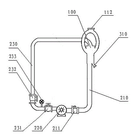
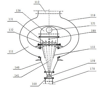
[0010] see figure 1 and figure 2 , the liquid-gas mixer 100 involved in the present invention is mainly composed of an interconnected power drive chamber 120 and a jet mixing chamber, both of which are vertical or horizontal, and the power drive chamber is located in the Above the jet mixing chamber (vertical type) or front end (horizontal type, etc.), the liquid-gas mixer is provided with the partition 131 of the power drive chamber and the jet mixing chamber, and several injection pipes are installed on the partition 132. For example, it can be fixedly welded or fastened with fastening nuts from above, below, or from left and right. The inlet end of the injection pipe is located in the power driving chamber, and the outlet end is located in the jet mixing chamber.

[0011] Preferably, the jet form of each spray pipe is preferably substantially non-diffused or less diffused, so that these small jet streams 141 can be converged into a tapered large jet with a water cross sec...


PUM


Abstract

The invention relates to a liquid-gas mixer and a gas-liquid recovery device by employing the liquid-gas mixer, the mixer is composed of a power drive chamber and a jet mixing chamber which are mutually connected, several jet pipes are arranged on a separator plate in the power drive chamber, the inlet end of the jet pipe is positioned on in the power drive chamber, the outlet end is positioned in the jet mixing chamber, the jet mixing chamber is composed of a suction chamber, a reducing pipe, a trunnion and a increasing pipe which are connected in order from up to down or from left to right, a pressure liquid inlet is arranged on the power drive chamber, an inlet of gas to be treated is arranged in the jet mixing chamber, the gas-liquid recovery device comprises the liquid-gas mixer and a pressurization circulating system, and a liquid discharge pipe is connected to a liquid return pipe of the pressurization circulating system. The liquid-gas mixer and the gas-liquid recovery device have the advantages of good liquid-gas mixing effect, low energy consumption, large processing amount and low operation cost, and are especially adapted to liquid substance recovery in a certain gaseous substance, such as recovery of waste vapour in flue gas.

Description

technical field [0001] The invention relates to a liquid-gas mixer and a gas-liquid recovery device using the mixer. Background technique [0002] At present, most of the devices involving the mixing of different fluid media are reactors equipped with stirrers used in chemical industry, and there are also devices that use the momentum of the medium flow itself for stirring and mixing. These mixing devices are generally used to realize the mixing of gases and gases. Or liquid-to-liquid mixing to mix different reactants together for corresponding reactions. For the mixing between gas and liquid, a process tower, such as a spray tower, is generally used, and the liquid is sprayed downward from the nozzle on the top of the tower, and the gas flows forward or backward to realize the dissolution of the gas or the transmission between them. Another example is a bubble tower, the liquid enters the tower from the top and flows downward, forming a liquid surface of a certain thicknes...

Claims


Application Information

Patent Timeline
Patent Type & Authority Applications(China)
IPC IPC(8): B01F5/02B01D53/18
Inventor 顾卫荣
Owner 山东信开源科技创新发展有限责任公司
Learn More