
Offshore wind driven generator set and mounting method thereof

A wind turbine and wind direction technology, which is applied in the direction of wind motor combination, wind engine, wind power generation, etc., can solve the problems of insufficient wind energy capture, large distance from wind turbines, poor stability, etc., achieve shallow draft, reduce installation difficulty, Ease of Migration

Inactive Publication Date: 2015-08-05
刘莹
View PDF8 Cites 9 Cited by
  • Summary
  • Abstract
  • Description
  • Claims
  • Application Information

AI Technical Summary

Problems solved by technology

However, multiple units are installed together and facing the wind at the same time, so there is turbulence caused by the wind rotors and interference with the wind flow that hits the adjacent wind rotors, so the distance between the wind turbines needs to be large enough, and a larger boat platform
Otherwise, it will lead to insufficient capture of wind energy and waste of resources, but a larger ship-type platform will inevitably bring about problems such as poor stability

Method used


Image

  • Offshore wind driven generator set and mounting method thereof
  • Offshore wind driven generator set and mounting method thereof
  • Offshore wind driven generator set and mounting method thereof

Examples


Embodiment Construction

[0038] The present invention will be further described below in conjunction with accompanying drawing. These drawings are all simplified schematic diagrams, and only illustrate the basic structure and assembly method of the present invention in a schematic manner.

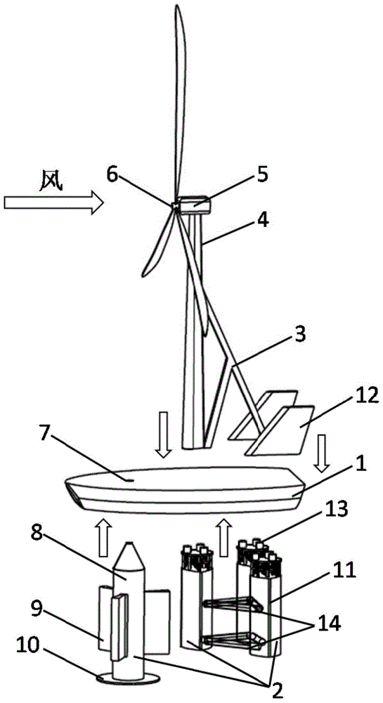
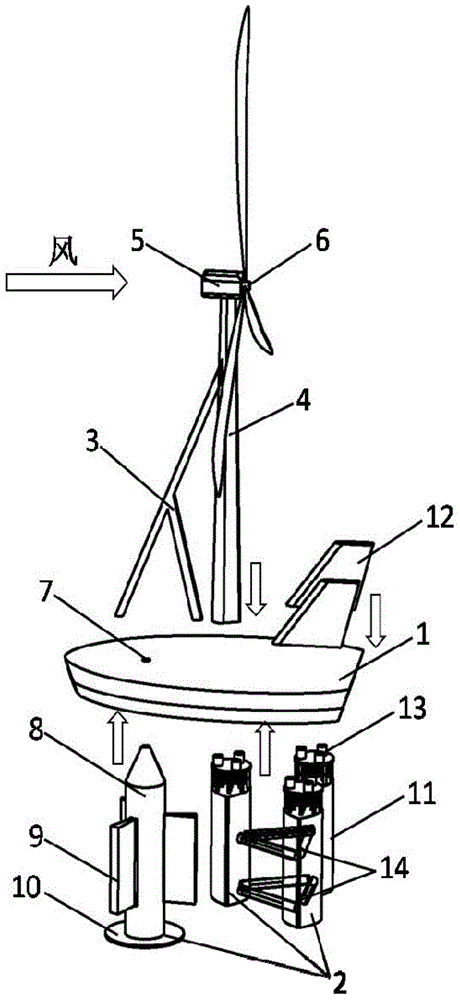
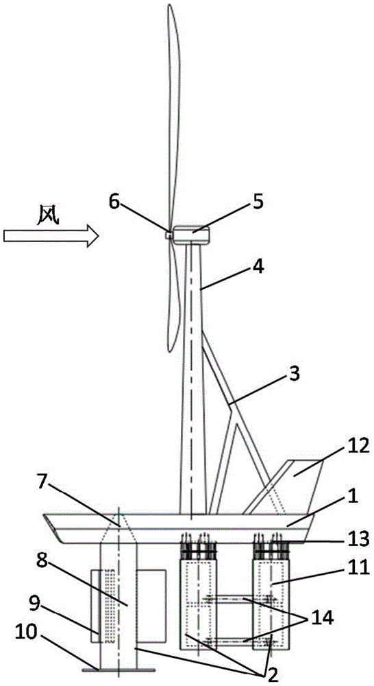
[0039] Such as figure 1 , 2 , 3, and 4, the boat platform 1 adopts a flat-bottomed barge structure, and a yaw cone slewing bearing 7 is installed on the front part (windward side) of the boat platform 1; a tower is fixed behind the yaw cone slewing bearing 7. The frame 4 and the cross section of the tower frame 4 adopt shapes such as drop shape, oval shape or ellipse shape with small wind resistance, and are rigidly connected with the nacelle of the wind power generating set. When the impeller 6 is arranged in the upwind direction in front of the tower 4, as figure 1 , 3 , the diagonal brace 3 is installed on the leeward side of the tower 4; when it is arranged in the downwind direction behind the tower 4, such...


PUM


Abstract

The invention discloses an offshore wind driven generator set and a mounting method thereof. The offshore wind driven generator set comprises a semi-submersible type floating body, a ship type platform, a tower, a cabin, impellers, vertical tail wings, an inclined supporting rod and the like, wherein the semi-submersible type floating body comprises a front floating barrel and at least one rear floating barrel; the upper part of the front floating barrel is conical, is inserted into a yaw tapered rotary bearing, and an anchoring system is connected to the middle lower part of the front floating barrel; a truss structure is arranged above a water level of each rear floating barrel, a dowel pin is arranged at the top of each rear floating barrel and is rigidly connected with a positioning device; a pressure equalizing tube is connected with each rear floating barrel. The ship type platform adopts a gabbart mode, the yaw tapered rotary bearing is arranged on the front section of the ship type platform, the tower is mounted behind the ship type platform, and symmetrical vertical tail wings are arranged at the tail part of the ship type platform. When the impellers are distributed in upwind direction (downward direction) in front (back) of the tower, the inclined supporting rod is mounted on the leeside surface (windward side surface) of the tower. The offshore wind driven generator set can be structurally mounted in a shipyard, so that the offshore mounting difficulty is lowered and the cost is reduced, the mechanical yaw failure rate is low and the reliability is high. The tower structure has an obvious damping effect, and the anti-overturning capability of the tower can be improved by the inclined supporting rod.

Description

technical field [0001] The invention relates to an offshore wind power generating set and an installation method thereof, in particular to an offshore wind power generating set adopting a floating support structure and an overall yaw of a wind turbine and an installation method thereof. Background technique [0002] Offshore wind turbines usually consist of three parts: tower head, tower frame and support structure. Since offshore wind resources are mostly distributed within 5-50km from the coast, and the water depth in these areas is mostly more than 50m, according to the current practice of fixing various through-pile structures on the seabed in offshore wind farms, compared with onshore wind farms, offshore wind farms Among the total construction costs, the investment in supporting structures is significantly higher than that of offshore and onshore wind farms. In addition to the construction cost of supporting structures, the installation cost of offshore wind turbines ...

Claims


Application Information

Patent Timeline
Patent Type & Authority Applications(China)
IPC IPC(8): B63B35/00F03D9/00
CPCY02E10/72Y02E10/727
Inventor 刘莹吴涵延王珊罗院明
Owner 刘莹
Learn More