Non-common-optical-path loop radial shear polarization phase shift interferometer

A ring path direction shearing and phase shifting interference technology is applied in the field of non-common optical path ring path direction shearing polarization phase shifting interferometer. Affect measurement accuracy and other issues to achieve the effect of improving data processing speed and algorithm accuracy, small measurement dynamic range, and low measurement accuracy

Inactive Publication Date: 2015-08-05
SICHUAN UNIV
View PDF5 Cites 4 Cited by
  • Summary
  • Abstract
  • Description
  • Claims
  • Application Information

AI Technical Summary

Problems solved by technology

However, since the four groups of light paths of the four interferograms generated by this structure pass through different parts of the optical element, it will cause problems such as uneven light distribution and inaccurate phase shift, which will affect its measurement accuracy.
In addition, the four-step spatial phase shift in the patent "Common Optical Path Shearing Interferometer Based on Four-step Spatial Phase Shift" (patent application number: 201010034142.3) has a complex structure and a large number of devices, which increases the source of measurement errors
The common optical path structure in the patent "Common Optical Path to Shearing Liquid Crystal Phase-Shifting Interference Wavefront Sensor" (patent application number: 20121076291.0) requires high precision in the installation and adjustment of optical components, especially the requirement that the two lenses have a common optical axis and a common focus. Difficult to implement in practice

Method used


Image

  • Non-common-optical-path loop radial shear polarization phase shift interferometer
  • Non-common-optical-path loop radial shear polarization phase shift interferometer
  • Non-common-optical-path loop radial shear polarization phase shift interferometer

Examples


Embodiment Construction

[0030] Combine below Attached picture The present invention is described in detail by way of examples. It is necessary to point out that the following examples are only used for further description of the present invention, and cannot be interpreted as limiting the protection scope of the present invention, and those skilled in the art make some non-essential improvements to the present invention according to the above-mentioned content of the present invention And adjustments still belong to the protection scope of the present invention.

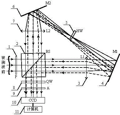
[0031] as shown in the picture 1 As shown, the non-common-optical path ring-path shear polarization phase-shift interferometer based on polarizer and 1 / 2 wave plate structure includes: polarizer P1, beam splitting prism BS2, lens L 1 3. Mirror M 1 4. 1 / 2 wave plate HW5, mirror M 2 6. Lens L 2 7. 1 / 4 wave plate QW8, analyzer A9, photocoupler CCD10 and computer 11. Polarizer P1 and 1 / 2 wave plate HW5 form a polarization modulation sy...


PUM


Abstract

The invention provides a non-common-optical-path loop radial shear polarization phase shift interferometer which is formed by a polarization modulation system, a loop radial shearing system, an N-step phase shifting system and an imaging system. A detected wave moves forward to enter into the polarization modulation system to be linearly polarized light which goes through the loop radial shearing system to be two beams of widened and narrowed orthogonal polarized light, then the light is processed by the N-step phase shifting system to be two round polarized light with opposite rotation directions, an interference phenomenon is generated through the polarization analyzer, the imaging system collects N interference fringe patterns, a corresponding phase shift algorithm is used to reconstruct the phase distribution shearing wave-front, and an iterative method or Zernike polynomial fitting is used to separate detected wave-front from the shearing wave-front. According to the non-common-optical-path loop radial shear polarization phase shift interferometer, a special reference mirror is not needed, a non-common-optical-path structure is used to reduce the difficulty of alignment, thus the measurement is more simple and convenient, the N-step phase shift technology is used to recover the wave-front, and the data processing speed and arithmetic accuracy of phase extraction are improved.

Description

technical field [0001] The invention relates to a technical field of wavefront detection based on circular radial shearing interferometry (CRSI, Cyclic Radial Shearing Interferometry) and polarization phase shifting technology, especially a non-common optical path circular direction Shear polarization phase-shifting interferometer. Background technique [0002] Wavefront sensors that measure wavefront phase based on the principle of interferometry have attracted widespread attention due to their high spatial resolution and high measurement accuracy. Typical interferometric wavefront sensors include Hartmann sensors, shearing interferometers, and point diffraction interferometers. [0003] The Hartmann sensor uses a microlens array to measure the slope of the incident beam, and reconstructs the wavefront based on the measured wavefront phase gradient data. Hartmann sensors treat each microlens as a sub-aperture, so the size of the microlens array determines the spatial samp...

Claims


Application Information

Patent Timeline
Patent Type & Authority Applications(China)
IPC IPC(8): G01J9/02
Inventor 李大海章辰王琴刘春玲
Owner SICHUAN UNIV
Why Eureka
Try Eureka