Method and system for supplying power to equipment using thermoelectric generation of pipelines

A technology of thermoelectric power generation and thermoelectric power generation sheet, which is applied in the directions of generators/motors, battery circuit devices, current collectors, etc., can solve problems such as difficulty in making full use of fluid temperature, poor soil thermal conductivity, and disappearance of temperature difference between hot and cold surfaces of power generation sheets.

Active Publication Date: 2015-08-12
北京暖流科技有限公司
View PDF6 Cites 5 Cited by
  • Summary
  • Abstract
  • Description
  • Claims
  • Application Information

AI Technical Summary

Problems solved by technology

[0003] The Chinese patent "A device for power generation by using the surface temperature difference of oil and gas pipelines (People's Republic of China, application number: 201420195588.6)" proposes a device for power generation by using the surface temperature difference of oil and gas pipelines, which uses the temperature between the surface of oil and gas pipelines and the external environment Although this method can realize power generation theoretically, it has the following disadvantages: First, the hot surface of the power generation sheet is in direct contact with the wall of the pipe, and the outer wall of the pipe is inevitably uneven and even corroded. and other problems, the contact thermal resistance of the wall surface of the power generation sheet is large, and it is difficult to make full use of the temperature of the fluid; the second is the method of using the ambient temperature to maintain the cold surface. Generally speaking, oil and gas pipelines are buried underground, and the thermal conductivity of the soil is poor. As the power generation process progresses, the temperature of the soil in the external environment will gradually increase, which will easily cause the temperature difference between the hot and cold surfaces of the power generation sheet to disappear, and the power generation capacity will be lost. The simultaneous loss of energy "quality" and "quantity"

Method used


Image

  • Method and system for supplying power to equipment using thermoelectric generation of pipelines
  • Method and system for supplying power to equipment using thermoelectric generation of pipelines
  • Method and system for supplying power to equipment using thermoelectric generation of pipelines

Examples


Embodiment 1

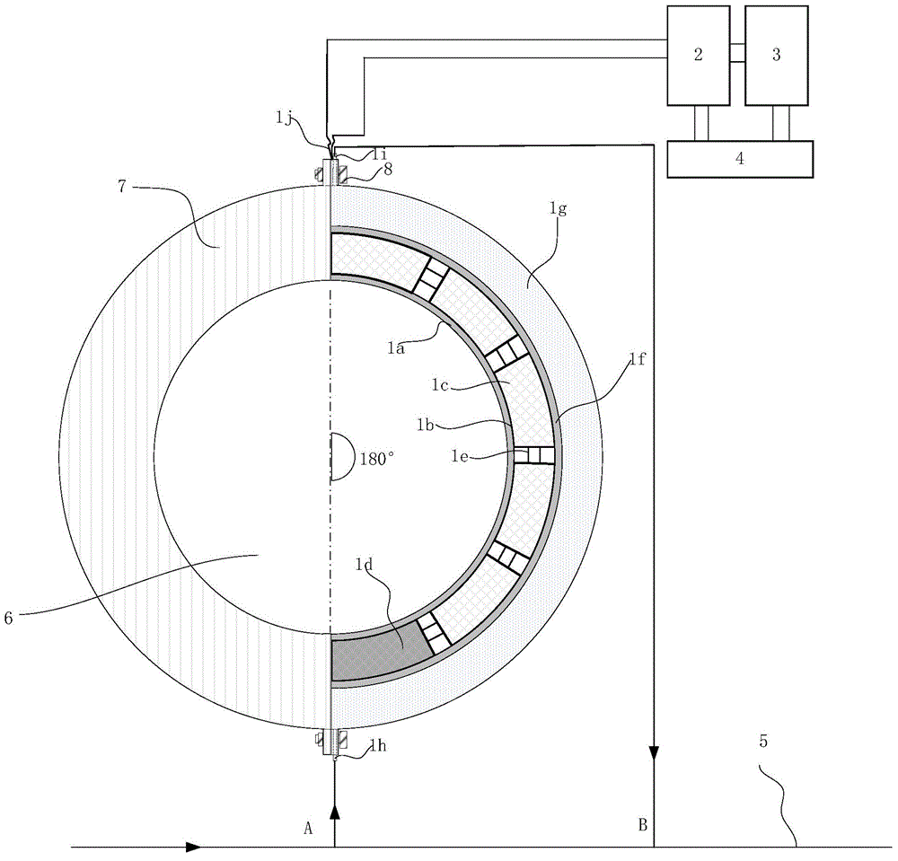
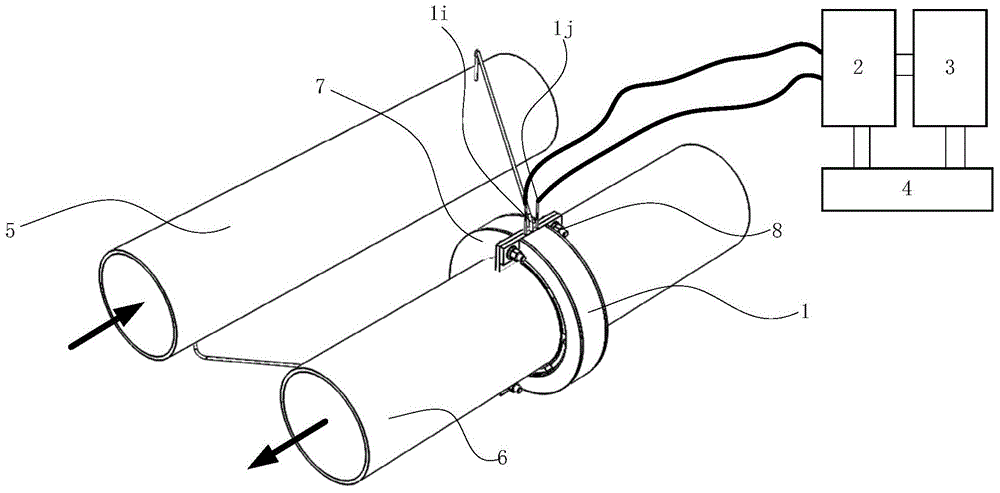
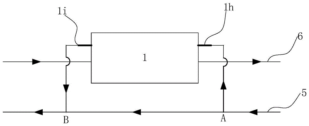
[0066] see figure 1 , figure 2 , image 3 .

[0067] A system for supplying power to equipment using temperature difference power generation in pipelines, comprising a temperature difference power generation system 1, a control circuit 2, an electrical storage device 3, equipment requiring power supply 4, a first pipeline 5 and a second pipeline 6, a fastening dual ring 7, and a tight 8 solid bolts are formed.

[0068] The thermoelectric power generation system 1 consists of an inner layer of compact heat-conducting material layer 1a, a thermoelectric chip arrangement chamber 1b, a thermoelectric chip group 1c, a pseudo-thermoelectric chip group 1d, an internal connection electrode 1e of the power chip, a middle compact thermal conductive material layer 1f, and a fluid The circulation chamber 1g, the inlet 1h of the fluid circulation chamber, the outlet 1i of the fluid circulation chamber, and the electric energy output electrode 1j of the thermoelectric generation sheet g...

Embodiment 2

[0073] see Figure 4 with Figure 5 .

[0074] A system that utilizes fluid temperature difference power generation to supply power to equipment, including a temperature difference power generation system 1, a control circuit 2, an electrical storage device 3, equipment requiring power supply 4, a first pipeline 5 and a second pipeline 6, a fastening dual ring 7, and a tight 8 solid bolts are formed.

[0075]The thermoelectric power generation system 1 consists of an inner layer of compact heat-conducting material layer 1a, a thermoelectric chip arrangement chamber 1b, a thermoelectric chip group 1c, a pseudo-thermoelectric chip group 1d, an internal connection electrode 1e of the power chip, a middle compact thermal conductive material layer 1f, and a fluid The circulation chamber 1g, the inlet 1h of the fluid circulation chamber, the outlet 1i of the fluid circulation chamber, and the electric energy output electrode 1j of the thermoelectric generation sheet group. The in...


PUM


Abstract

The invention relates to a method and a system for supplying power to equipment using thermoelectric generation of pipelines and particularly relates to a method and a system for supplying power to equipment using a temperature difference of fluids in supply and return pipes of a heat supply or air-conditioning system. As the supply pipe and the return pipe of the heat supply or the air conditioning system have a stable temperature difference, fluids of high and low temperatures are guided into a thermal-cooling cycling cavity of a generating sheet generation system, the temperature difference between cold and hot surfaces of a generating sheet is maintained stable for stable power generation, and a control circuit is used for supplying power to the equipment or charging an electrical storage device. The circulation power of the fluids in the cycling cavity is from a pressure difference of the supply pipe and the return pipe of the heat supply or the air conditioning system and a pressure difference of a certain distance between an upstream and a downstream of the same pipe.

Description

technical field [0001] The invention belongs to the field of energy technology, and relates to a method for generating power to equipment by utilizing temperature difference in pipelines, in particular to a method for generating power for equipment by using the temperature difference to generate power for equipment when there is a temperature difference in the fluid in the water supply and return pipelines of a heating or air-conditioning system. It also relates to a system for implementing power supply of equipment by using the method. Background technique [0002] In the field of heating and air conditioning, the measurement of pressure, temperature, flow and other parameters of traditional water systems mostly use mechanical instruments, which can read, collect and record measurement data through dial display, manual reading, and pen and paper records. The operation of the system is then managed based on these read or recorded data. With the development of automatic cont...

Claims


Application Information

Patent Timeline
Patent Type & Authority Applications(China)
IPC IPC(8): H02J7/32H02N11/00
CPCH02N11/002
Inventor 不公告发明人
Owner 北京暖流科技有限公司
Why Eureka
Try Eureka