Special-purpose drill for hole drilling

A drill bit and drill shank technology, which is applied in the direction of wood drilling tools, wood processing tools, wood turning tools, etc., can solve the problems of large drill bit wear, workpiece becoming waste products, and small drill bit wear, so as to improve labor efficiency and labor accuracy , Reduce the probability of product reimbursement, the effect of simple structure

Inactive Publication Date: 2015-08-19
启东市吕四科技创业中心有限公司
View PDF0 Cites 2 Cited by
  • Summary
  • Abstract
  • Description
  • Claims
  • Application Information

AI Technical Summary

Problems solved by technology

[0004] The drill bit is a commonly used tool for drilling. When the drill bit is drilling, it mainly cuts the workpiece through the top of the cutter head, and discharges the debris through the chip discharge groove. If the debris cannot be discharged smoothly, it will cause the inner wall of the drilled hole to appear. Scratches may even cause the workpiece to become a waste product. When designing the drill bit, the helix angle of the chip removal flute directly affects the chip removal speed. The larger the helix angle, the smoother the chip removal. However, the debris will also wear more on the drill bit. The smaller the angle, the slower the chip removal, and the relatively less wear on the drill bit. The existing drill bit is usually equipped with three chip removal grooves, and the chip removal grooves are relatively narrow, so the helix angle is usually smaller, and the chip removal is slower, which is easy to cause holes. Scratches on the inner wall

Method used


Image

  • Special-purpose drill for hole drilling

Examples


Embodiment Construction

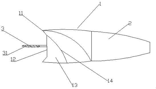
[0017] The invention relates to a special drill bit for drilling, such as figure 1 Shown: includes drill bit 1 and drill handle 2, drill bit 1 and drill handle 2 are fixedly connected, drill bit 1 includes a depth limiting device and a drill tip 3 arranged in the depth limiting device, and the drill tip 3 is provided with a spiral chip removal Groove 31, the helix angle of the flute 31 is 15-30°; the drill shank 2 is set as a cylindrical drill shank as a whole, and the diameter of the cylindrical drill shank is gradually decreasing from the other end away from the drill bit 1 to the tail end of the drill shank 2 , forming a round table-shaped drill shank as a whole,

[0018] Such as figure 1 As shown: the overall structure of the depth limiting device is: the depth limiting device is mainly a thickness limiting structure 13, and the drill tip 3 runs through the entire drill bit 2 with the center axis of the depth limiting device as the axis.

[0019] The thickness limiting s...


PUM


Abstract

The invention discloses a special-purpose drill for hole drilling. The special-purpose drill for hole drilling comprises a drill body and a drill stock, wherein the drill body is fixedly connected with the drill stock; the drill body comprises a depth limiting device and a drill tip arranged in the depth limiting device; the drill tip is provided with a spiral chip groove; the whole drill stock is a cylindrical drill stock; the diameter of the cylindrical drill stock is sequentially reduced gradually from the other end which is far away from the drill body to the tail end of the drill stock so that the frustum-shaped drill stock is formed; the depth limiting device has a thickness limiting structure mainly; a central axis of the depth limiting device serves an axis of the drill tip; and the drill tip penetrates in the whole drill. The special-purpose drill for hole drilling has the advantages that the special-purpose drill for hole drilling comprises the depth limiting device and the drill tip arranged in the depth limiting device, the drill tip is provided with the spiral chip groove, a helical angle of the chip groove is 15-30 degrees, chips can be removed effectively, the probability of scrappage of products is reduced, by the depth limiting device, a required hole drilling depth can be confirmed effectively, wood cannot be pierced thoroughly, and the work efficiency and the work accuracy are improved.

Description

technical field [0001] The invention relates to a special drill bit for drilling, which belongs to the field of machining tools. Background technique [0002] Drills are tools used to drill through holes or blind holes in solid materials and to ream existing holes. Commonly used drills mainly include twist drills, flat drills, center drills, deep hole drills and casing drills. [0003] In construction engineering, an electric drill is a commonly used tool. The user can drive the motor through electric power to make the drill bit rotate rapidly to drill holes for subsequent operations. In this process, the depth of the hole is an important parameter, which needs to be adjusted according to specific needs. [0004] The drill bit is a commonly used tool for drilling. When the drill bit is drilling, it mainly cuts the workpiece through the top of the cutter head, and discharges the debris through the chip discharge groove. If the debris cannot be discharged smoothly, it ...

Claims


Application Information

Patent Timeline
Patent Type & Authority Applications(China)
IPC IPC(8): B27G15/00
CPCB27G15/00
Inventor 彭包军
Owner 启东市吕四科技创业中心有限公司
Why Eureka
Try Eureka