Optical fiber image transmission-based detection system for cylinder surface microscratch defect

A detection system and cylindrical surface technology, applied in the direction of measuring devices, material analysis through optical means, instruments, etc., can solve problems such as difficulty in adapting to insufficient light, cumbersome mechanical and electrical structures, complex control systems, etc., and achieve roughly the same measurement error , simplified operation, and convenient data processing

Active Publication Date: 2015-08-19
HUAZHONG UNIV OF SCI & TECH
View PDF6 Cites 9 Cited by
  • Summary
  • Abstract
  • Description
  • Claims
  • Application Information

AI Technical Summary

Problems solved by technology

[0005] Among the two technologies mentioned above, although the circumference detection can be realized, there are many deficiencies: ① Whether it is the laser projection method or the CCD imaging method, only the local information of the cylindrical object to be measured can be obtained each time; the former laser sensor The probe needs to rotate 180° back and forth around the product, and the latter CCD camera needs to scan and shoot circumferentially along the cylinder to complete the defect detection on the entire outer cylindrical surface of the part
Such a measurement method is not only inefficient, but also requires a corresponding rotating mechanism and a complex control system. The mechanical and electrical structure is cumbersome, the operation is complicated, and coordination and control are difficult. It cannot meet the needs of high-efficiency, low-cost, and high-intelligence social production; ②The abo

Method used


Image

  • Optical fiber image transmission-based detection system for cylinder surface microscratch defect
  • Optical fiber image transmission-based detection system for cylinder surface microscratch defect
  • Optical fiber image transmission-based detection system for cylinder surface microscratch defect

Examples


Example Embodiment

[0033] In order to make the objectives, technical solutions and advantages of the present invention clearer, the following further describes the present invention in detail with reference to the accompanying drawings and embodiments. It should be understood that the specific implementation examples described here are only used to explain the present invention, but not to limit the present invention. In addition, the technical features involved in the various embodiments of the present invention described below can be combined with each other as long as they do not conflict with each other.

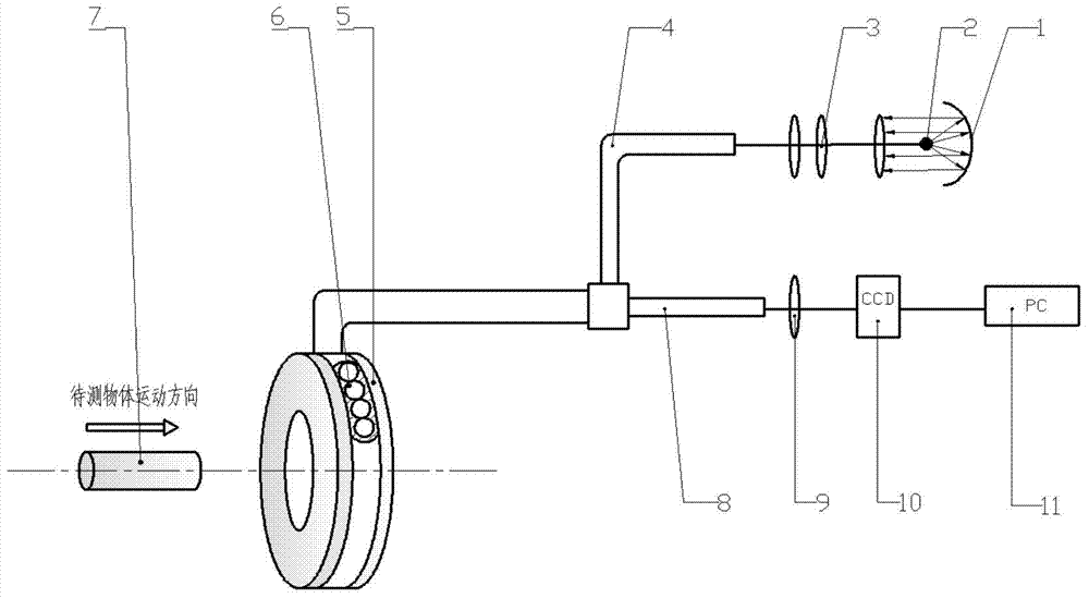
[0034] In recent years, optical fiber image transmission and photoelectric detection have been widely used in various fields. At present, the main methods used to transmit images are traditional optical systems, fiber bundle image transmission, CCD, and the emerging CMOS method. Traditional optical systems (such as microscopes, telescopes, etc.) are not easy to reduce in weight and volume, r...


PUM


Abstract

The invention discloses an optical fiber image transmission-based detection system for cylinder surface microscratch defects. A fiber optics bundle image transmission principle is used to regularly arrange image transmission optical fibers on one concentric circumference, thus realizing image acquisition and defect detection on the circumference of the outer surface of a cylinder. A device mainly comprises a spherical condensation mirror, a point light source, a focusing lens system, light transmitting optical fibers, a self-focusing bar lens, the image transmission optical fibers, a cylindrical lens and a linear array CCD (Charge Coupled Device). On one hand, external illumination light is led in by the light transmitting optical fibers, so that an annular detection area of a detected surface is sufficiently illuminated; on the other hand, the image transmission optical fibers are used for transmitting reflected light on the detected surface to a CCD focusing lens system; finally, outer surface defects of a cylinder-type object are analyzed and detected by an image capture card and computer software. The device is simple in structure; when a closed revolving surface is detected, the microscratch defects of the whole circumference of the surface of the cylinder can be detected in real time without rotating the to-be-detected object or the linear array CCD.

Description

Technical field [0001] The invention belongs to the field of photoelectric detection technology, and more specifically, relates to a detection system for micro-mark defects on the cylindrical surface based on optical fiber image transmission. Background technique [0002] With the development of modern production and processing technology, there are higher requirements for the inspection speed and accuracy of processed parts or other products, and the inspection technology is also developing in the direction of high-speed, high-precision, non-contact and online inspection. At present, there have been some researches on the non-contact circumferential surface detection technology based on photoelectric detection at home and abroad. In summary, there are mainly laser projection method and CCD imaging method. [0003] The working principle of the laser projection method is to place the object to be measured in a parallel light source and project it onto the receiving surface of the ph...

Claims


Application Information

Patent Timeline
IPC IPC(8): G01N21/952
Inventor 王平江邹尚波刘权
Owner HUAZHONG UNIV OF SCI & TECH
Why Eureka
Try Eureka