Three-phase imbalance and low-voltage treatment device and system, and compensation loop switching method

A technology of balance compensation and low voltage, which is applied in the field of three-phase unbalance and low voltage control devices, and can solve problems such as switch burnout, single-phase burnout of distribution transformers, and unbalanced three-phase loads

Active Publication Date: 2015-08-19
HENAN BOTONG ELECTRIC POWER TECH
View PDF8 Cites 1 Cited by
  • Summary
  • Abstract
  • Description
  • Claims
  • Application Information

AI Technical Summary

Problems solved by technology

Unbalanced three-phase loads can reduce the power supply efficiency of lines and distribution transformers, or cause excessive overloading of heavy-loaded phases, which may cause serious consequences such as burning of a certain phase wire, switch burnout, and even single-phase burnout of distribution transformers.
[0005] 1. Line loss is proportional to the square of the passing current
The unbalanced three-phase load greatly increases the line loss. For example, the current of a certain phase is 3A, and the rest of the current is 0. If it can be evenly distributed to the three phases and become 1A per phase, the line loss will be reduced to 1 / 3 of the original line loss. In addition, if the three-phase imbalance is considered, it will also cause current in the neutral line, which will also cause loss in the neutral line, and the line loss will drop more
[0006] 2. The distribution transformer is the main power supply equipment of the low-voltage power grid. When it operates under the condition of unbalanced three-phase load, it will increase the loss of the distribution transformer, because the power loss of the distribution transformer is the same as the load capacity. Consumption and iron consumption are proportional to the degree of imbalance
The winding insulation of the distribution transformer ages faster due to overheating, resulting in a reduction in equipment life
[0010] 4. When the three-phase load is unbalanced, the output current of each phase of the distribution transformer is not equal, and the internal three-phase voltage drop is not equal, which will inevitably lead to the three-phase unbalance of the output voltage of the distribution transformer
The application does not give an effective reactive power compensation device, and it cannot solve the three-phase unbalance and low voltage problems

Method used


Image

  • Three-phase imbalance and low-voltage treatment device and system, and compensation loop switching method
  • Three-phase imbalance and low-voltage treatment device and system, and compensation loop switching method
  • Three-phase imbalance and low-voltage treatment device and system, and compensation loop switching method

Examples


Embodiment 2

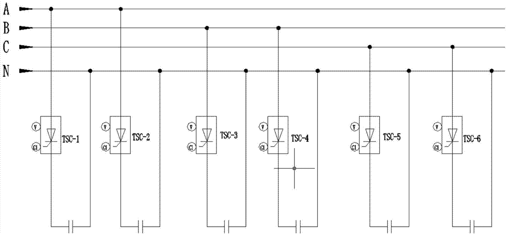
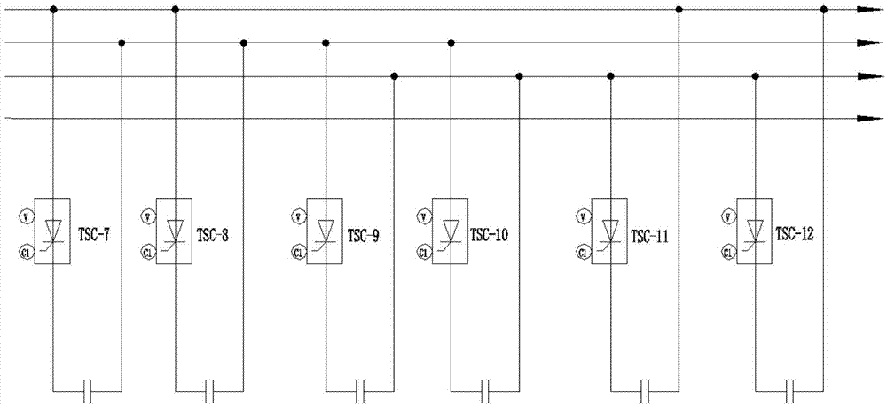
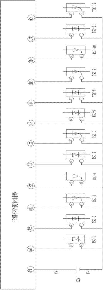
[0140] The difference between this embodiment and the above-mentioned embodiment 1 of the unbalanced compensation capacitor switching method is that in embodiment 1, there are two compensation lines between phases, and each compensation line is connected in series with a thyristor and a capacitor. When inputting, the two capacitors need to be controlled successively. In this embodiment, there is only one compensation line between phases. This line is connected with a thyristor and a capacitor in series. When inputting the capacitor, only one time is required. Just put in control. Among them, the connection relationship between the capacitor and the three-phase line is as follows: Figure 5 As shown, the connection relationship between the controller and the capacitor is as follows Figure 6 shown.

[0141] The method of unbalance compensation capacitor switching is as follows:

[0142] The capacitors corresponding to the A3, B3, and C3 output terminals on the three-phase un...

Embodiment 1

[0191] The three-phase unbalance and low voltage control system in this embodiment has been described in detail in Embodiment 1 of the unbalance compensation capacitor switching method, and will not be repeated here.

[0192] Three-phase unbalance and low voltage control system embodiment 2

[0193] The embodiment of the three-phase unbalance and low voltage control system in this embodiment has been described in detail in Embodiment 2 of the unbalance compensation capacitor switching method, and will not be repeated here.

[0194] Embodiment 1 of three-phase unbalance and low voltage control device

[0195] The embodiment of the device is the same as the first embodiment of the three-phase unbalance and low voltage control system, and will not be repeated here.

[0196] Embodiment 2 of three-phase unbalance and low voltage control device


PUM


Abstract

The invention relates to a three-phase imbalance and low-voltage treatment device and system, and a compensation loop switching method. The system comprises a collection unit for collecting three-phase current and voltage, a control unit, and an imbalance compensation unit. The imbalance compensation unit comprises at least one compensation circuit connected between any two phases. Each compensation circuit is provided with an imbalance compensation capacitor and a control switch in a series manner. The control unit is in control connection with the control switches. The method comprises an imbalance compensation capacitor switching-in and switching-off method, and the switching-in and switching-off of the corresponding capacitor is achieved through the corresponding control method. The device comprises a controller, and the controller employs the above imbalance compensation capacitor switching-in and / or switching-off method. The method provided by the invention can achieve the quick and accurate switching-in or switching-off of the capacitor, thereby effectively improving the power factor of each phase and guaranteeing the stability and reliability of reactive compensation.

Description

technical field [0001] The invention relates to a three-phase unbalance and low voltage control device, system and compensation circuit switching method, and belongs to the technical field of power grid reactive power compensation, three-phase unbalance and low voltage control. Background technique [0002] With the rapid development of the national economy and science and technology, the living standards of residents have been rapidly improved, and various advanced modern household appliances have quickly entered the family, and the electricity load of residents has also increased. The current household appliances used by residents are different from those in the past The ones used are very different. In the past, they were only incandescent lamps, electric rice cookers, and electric frying pans, but now they are energy-saving lamps, refrigerators, range hoods, hydraulic TVs, air conditioners, induction cookers, washing machines and other household appliances. , From the pe...

Claims


Application Information

Patent Timeline
Patent Type & Authority Applications(China)
IPC IPC(8): H02J3/26H02J3/16
CPCH02J3/16H02J3/26Y02E40/30Y02E40/50
Inventor 闫东超张永启
Owner HENAN BOTONG ELECTRIC POWER TECH
Why Eureka
Try Eureka