Crude oil emulsion fluid electrostatic coalescer

An electrostatic coalescence and emulsion technology, applied in the direction of electricity/magnetic dehydration/emulsion breaking, etc., can solve the problems of easy breakdown of electrodes, low coalescence efficiency, and inability to effectively use turbulent pulsation dielectrophoretic coalescence, etc. Achieve the effects of improving coalescence efficiency, enhancing processing capacity, and good coalescence effect

Active Publication Date: 2015-08-26
CHINA UNIV OF PETROLEUM (EAST CHINA)
View PDF5 Cites 8 Cited by
  • Summary
  • Abstract
  • Description
  • Claims
  • Application Information

AI Technical Summary

Problems solved by technology

[0007] In view of the problems that the internal electrodes of traditional electric dehydration equipment are easy to break down, the coalescence efficiency is low, and the turbulent flow and dielectrophoretic coalescence cannot be effectively used, the present invention provides a method that can effectively overcome the phenomenon of "collapsed electric field" and adapt to large water content. range, reasonably generate and use turbulent pulsations, and at the same time introduce an efficient and compact crude oil emulsion electrostatic coalescer for dielectrophoretic coalescence, thereby reducing the volume of downstream sedimentation equipment and reducing energy consumption in the electric dehydration process. Crude oil dehydration treatment in offshore oilfields provides a new type of crude oil emulsion electrostatic coalescer with small footprint, high efficiency, and easy disassembly

Method used


Image

  • Crude oil emulsion fluid electrostatic coalescer
  • Crude oil emulsion fluid electrostatic coalescer
  • Crude oil emulsion fluid electrostatic coalescer

Examples


Embodiment Construction

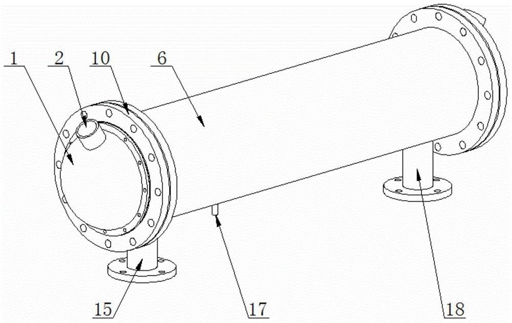
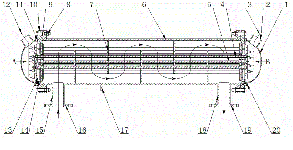
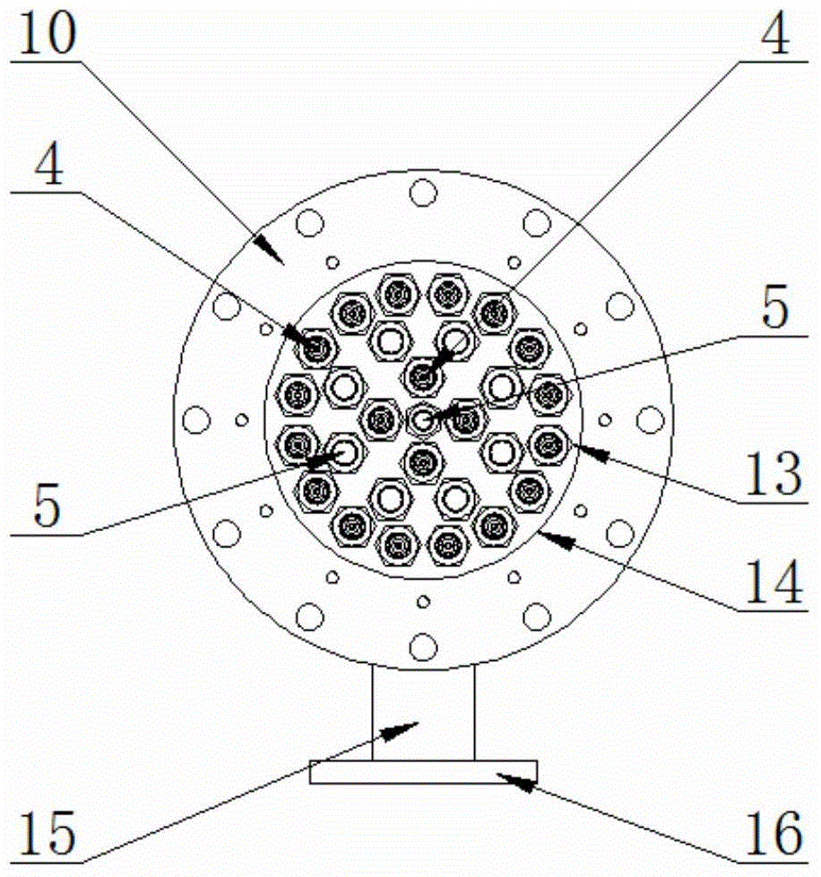
[0034] Reference attached figure 1 ~ attached Figure 7 , the present invention consists of a high / low voltage terminal cover 1, a high / low voltage cable lead hole 2, a low voltage cable 3, a high voltage columnar insulating electrode 4, a low voltage columnar insulating electrode 5, a coalescer cylinder 6, a baffle support plate 7, Insulation head fastening bolt 8, crude oil emulsion gasket 9, insulation head 10, transformer oil gasket 11, high voltage cable 12, electrode fixing sealing joint 13, stepped groove 14, inlet pipe 15, inlet connection Flange 16, barrel grounding terminal 17, outlet pipe 18, outlet connecting flange 19, fastening bolts 20 on the terminal face cover, high-voltage electrode guide hole 21, low-voltage electrode guide hole 22, electrode lead sealing joint 23, electrode insulation shell Tube 24, electrode terminal 25, fastening sealing thread 26, sealing rubber pad 27, electrode metal skeleton 28 and so on.

[0035] Reference attached figure 1 And at...


PUM


Abstract

The invention discloses a crude oil emulsion fluid electrostatic coalescer. The crude oil emulsion fluid electrostatic coalesce comprises a barrel which is of a cylindrical structure, wherein a grounding terminal inlet pipeline and an outlet pipeline are arranged on the outer side surface of the barrel; the two ends of the barrel are connected with an insulating end enclosure and end surface sealing covers; cable introducing holes which are used for introducing high/low-voltage cables and are connected with multiple high/low-voltage electrodes in the barrel are formed in the two end surface sealing covers respectively; a low-voltage electrode is arranged on an axis, and a high-voltage electrode is wound outside the axis in a concentric manner, and the high-voltage electrode is closest to the barrel housing; a plurality of foldout supporting plates for guiding the crude oil emulsion fluid and supporting high/low-voltage electrodes are arranged on the inner part of the barrel. The crude oil emulsion fluid electrostatic coalesce has the advantages of being compact in structure, small in floor space and convenient to dismount, is suitable for an oil-water separating process on the sea and improving original oil-water separating equipment; uneven electric fields are introduced to achieve good coalescence effect on uncharged liquid drops in the emulsion fluid with low moisture content, which is difficult to treat by dipole coalescence and electrophoresis coalescence through normal electric dehydrating equipment, so that the treatment capacity of electrostatic coalescence equipment is strengthened.

Description

technical field [0001] The invention relates to a crude oil emulsion electrostatic coalescence device, which is mainly used in the liquid electric coalescence dehydration process of land and offshore oilfield production, can realize rapid coalescence of water droplets in water-in-oil emulsion, has compact structure, and is convenient for transportation , The advantages of fast connection. Background technique [0002] Water-in-oil emulsions are widely found in petroleum, chemical and other industrial production processes. Dehydration of crude oil is a key link that the petroleum industry must go through. Chemical and physical methods are usually used to accelerate the thinning and rupture of the water droplet interface film to improve the coalescence efficiency. . Electrostatic coalescence technology is one of the commonly used methods in the crude oil dehydration process. Its basic principle is to apply a high-strength electric field to the emulsion to increase the collisi...

Claims


Application Information

Patent Timeline
Patent Type & Authority Applications(China)
IPC IPC(8): C10G33/02
Inventor 罗小明田成坤何利民吕宇玲吴宗强
Owner CHINA UNIV OF PETROLEUM (EAST CHINA)
Why Eureka
Try Eureka