Fuel gas processing method for FLNG (floating liquefied natural gas) oil-gas storage and offloading device

A technology of liquefied natural gas and liquefaction equipment, which is applied in the field of fuel gas treatment of floating liquefied natural gas oil and gas storage and unloading equipment, which can solve the problems of high energy consumption and achieve energy-saving and efficient operation, reduce waste, and reduce the liquefaction rate.

Active Publication Date: 2015-08-26
CHINA NAT OFFSHORE OIL CORP +1
View PDF7 Cites 8 Cited by
  • Summary
  • Abstract
  • Description
  • Claims
  • Application Information

AI Technical Summary

Problems solved by technology

[0003] In addition, due to the relatively large energy consumption required by the entire FLNG process unit, it is also necessary to consider that the scale of the fuel gas treatment unit should meet the operating requirements of the special offshore environment and reduce the occupied space as much as possible. However, the fuel gas system of the existing The gas treatment method cannot meet the fuel supply requirements in the special offshore environment, so it is necessary to propose a new fuel gas system treatment method to provide fuel power for the FLNG oil and gas treatment device

Method used


Image

  • Fuel gas processing method for FLNG (floating liquefied natural gas) oil-gas storage and offloading device
  • Fuel gas processing method for FLNG (floating liquefied natural gas) oil-gas storage and offloading device
  • Fuel gas processing method for FLNG (floating liquefied natural gas) oil-gas storage and offloading device

Examples


specific Embodiment

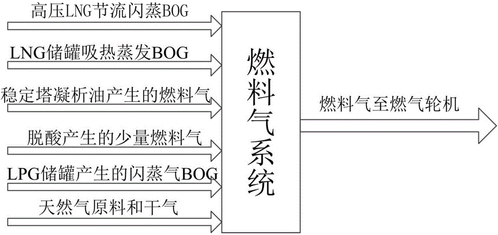
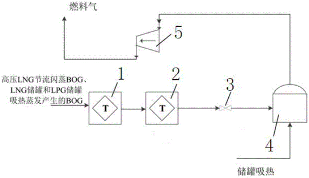
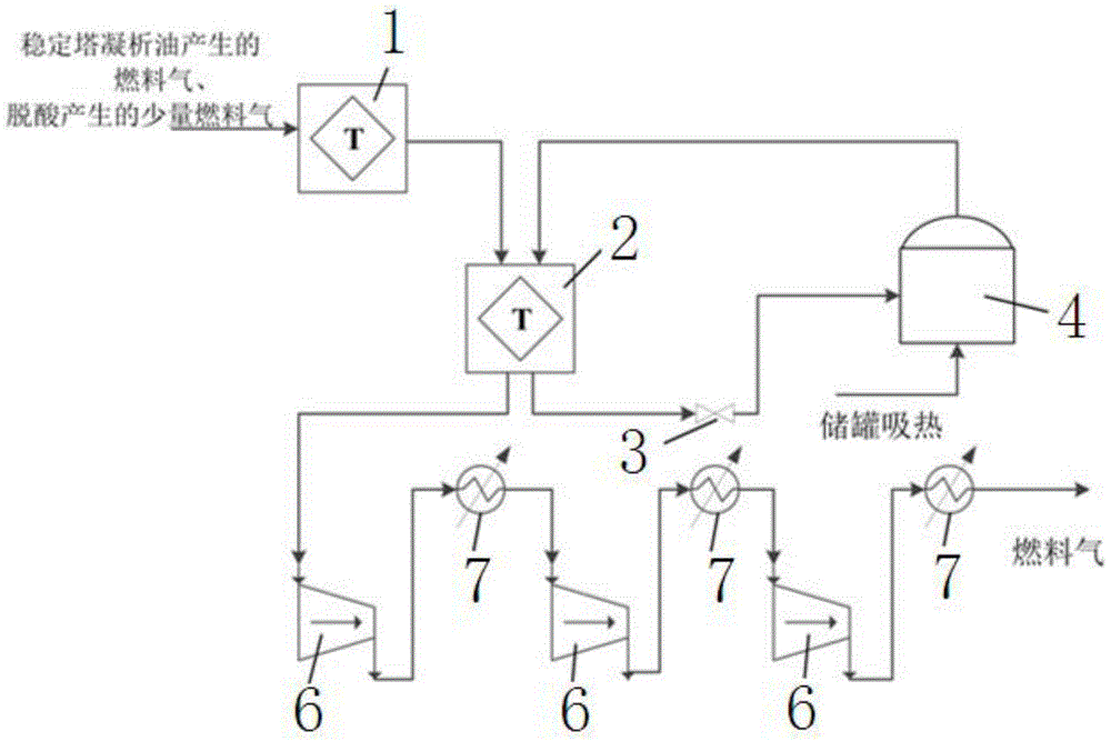
[0037] 1) Fuel gas sources include high-pressure LNG throttling flash BOG, BOG evaporated from LNG storage tanks, flash gas BOG from LPG storage tanks, fuel gas from condensate oil in the stabilization tower, and a small amount of fuel gas from deacidification , also includes the dry gas and natural gas produced by the light hydrocarbon recovery unit in the light hydrocarbon recovery process, including the specific parameters such as the temperature, pressure and flow rate of the fuel gas source, and the determinants of the various gas source parameters (as shown in Table 1).

[0038] Table 1 Characteristics of fuel gas source

[0039]

temperature °C

pressure bar

Flow t / h

Remark

High pressure LNG throttling flash BOG

-160

1.2

21.2

By optimizing the balance with the fuel gas system

LNG storage tank endothermic evaporation BOG

-160

1.2

6.2

Depends on the LNG storage tank; fixed value

Fuel gas from s...


PUM


Abstract

The invention relates to a fuel gas processing method for an FLNG (floating liquefied natural gas) oil-gas storage and offloading device. The method comprises the following steps: 1), multiple fuel gas sources are prepared; 2), a low-temperature compression system and a normal-temperature compression system are arranged, wherein the low-temperature compression system comprises a precooling device, a liquefying device, a throttle valve, an LNG storage tank and a low-temperature BOG (boil off gas) compressor, and the normal-temperature compression system comprises a precooling device, a liquefying device, a throttle valve, an LNG storage tank, three normal-temperature BOG compressors and three coolers; 3), the BOG obtained through high-pressure LNG throttling and flash evaporation, the BOG obtained through heat absorption and evaporation of the LNG storage tank and the BOG obtained through heat absorption and evaporation of an LPG (liquefied petroleum gas) storage tank are controlled to enter the low-temperature compression system, the fuel gas produced by condensate oil of a stabilizer and a small amount of fuel gas produced through deacidification are controlled to enter the normal-temperature compression system, a fuel gas low-temperature compression process and a fuel gas normal-temperature compression process are finished respectively; 4), technological process simulation software is adopted to calculate power consumption of each processing device and the total power consumption; 5), the processing process of the fuel gas sources is further optimized and analyzed. The fuel gas processing method can meet the operation requirement of the LFNG in a special maritime environment, and the operation safety and economy are improved.

Description

technical field [0001] The invention relates to a fuel gas processing method, in particular to a fuel gas processing method of a floating liquefied natural gas storage and unloading device. Background technique [0002] FLNG (floating liquefied natural gas production, storage and offloading device) is an offshore production facility that exploits natural gas from deep-sea gas fields and marginal gas fields and condenses it into LNG (liquefied natural gas). As a new development technology, FLNG has low investment, It is favored by many countries for its short construction period, easy migration, and environmental friendliness. As an independent FLNG, all processes and equipment must have the basic characteristics of land in principle. However, FLNG needs to consume a large amount of fuel gas to provide raw materials for gas turbines. The source and amount of fuel gas are directly related to the safe operation, energy consumption and economy of the entire FLNG. [0003] In ...

Claims


Application Information

Patent Timeline
Patent Type & Authority Applications(China)
IPC IPC(8): C10L3/10B63B25/14
Inventor 谢彬喻西崇李玉星王春升王武昌朱建鲁王清程兵李焱王世圣谢文会赵晶瑞冯加果李阳杜庆贵
Owner CHINA NAT OFFSHORE OIL CORP
Why Eureka
Try Eureka