
Integrated intelligent grouting system

An integrated and intelligent technology, applied in the test of infrastructure, construction, infrastructure engineering, etc., can solve the problems of difficulty in maintaining and cleaning specific gravity, difficult to guarantee the quality of grouting, unsafe electric valves, etc., to save labor and proportion. Accurate, less labor-intensive effect

Active Publication Date: 2016-11-09
CHINA THREE GORGES CORPORATION +1
View PDF6 Cites 1 Cited by
  • Summary
  • Abstract
  • Description
  • Claims
  • Application Information

AI Technical Summary

Problems solved by technology

[0008] The integrated intelligent grouting system provided by the present invention has the following six purposes: 1) to solve the problem of low efficiency, inaccurate proportioning, high labor intensity, time-consuming and labor-intensive use of existing manual grouting
2) Solve the problem of manual sampling and weighing method of cement slurry proportion measurement in the existing slurry preparation, which is time-consuming and labor-intensive, difficult to maintain and clean the proportion scale, discontinuous collection, and difficult to guarantee the quality of grouting
3) Solve the problems of energy waste caused by the existing grouting pump with high pressure and constant power output, and manual operation of high pressure and high pressure electric valves is unsafe and easy to cause casualties

Method used


Image

  • Integrated intelligent grouting system
  • Integrated intelligent grouting system
  • Integrated intelligent grouting system

Examples


Embodiment Construction

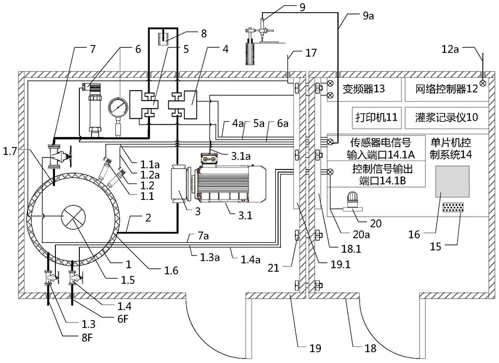
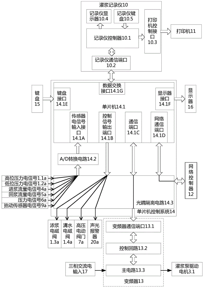
[0027] The integrated intelligent grouting system of this embodiment is composed of the following parts, which will be described one by one below.

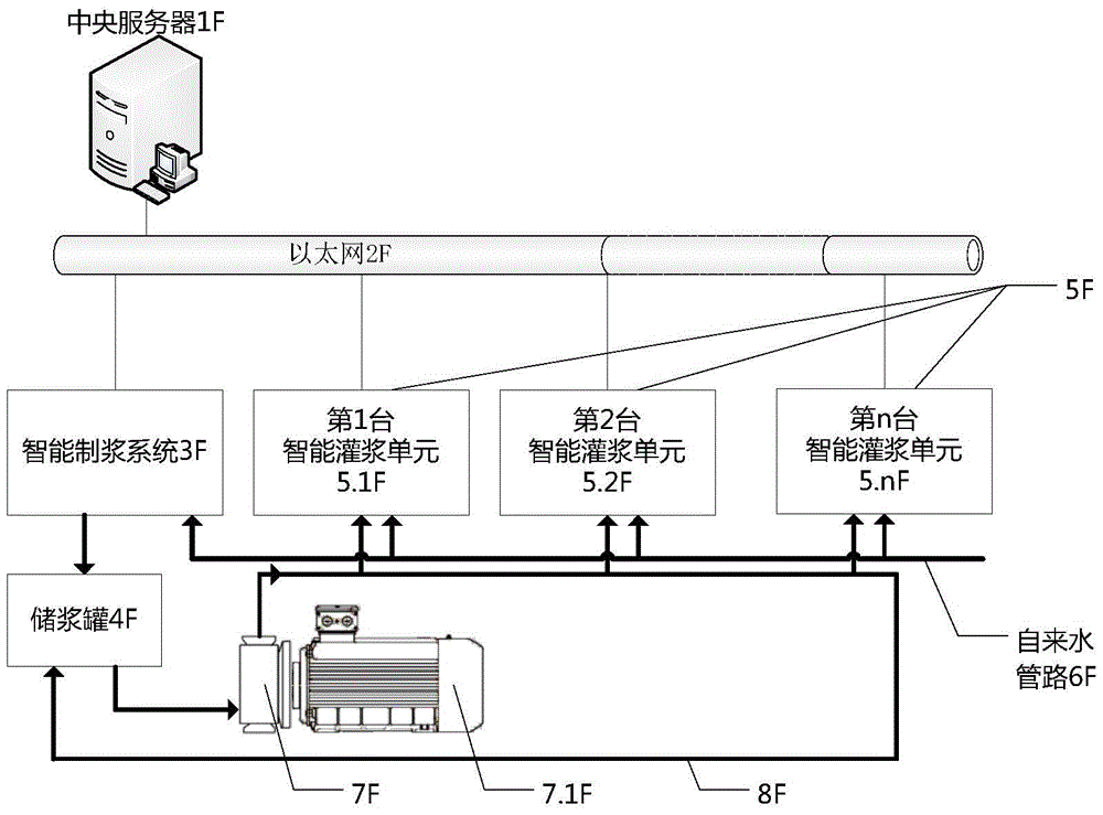
[0028] one sight figure 1 , set up an intelligent pulping system 3F for preparing thick slurry and n sets of intelligent grouting units 5F (respectively denoted as 5.1F, 5.2F, 5.nF), all communicated with the central server 1F through Ethernet 2F. A slurry storage tank 4F connected with the intelligent pulping system is also provided, and the slurry storage tank, the thick slurry delivery pump 7F, and n intelligent grouting units 5F are connected by a thick slurry delivery pipeline 8F to provide circulating thick slurry. The driving motor of the slurry pump for thick slurry is 7.1F. A tap water pipeline 6F is also provided to supply water to the intelligent pulping system 3F and n sets of intelligent grouting units. The thick slurry configured by the intelligent pulping system 3F is stored in the slurry storage tank 4F, and the...


PUM


Abstract

Disclosed is an integrated intelligent grouting system. A pulp feeding pump is employed to convey a thick pulp prepared by an intelligent pulp preparing system into a pulp storage tank and n intelligent grouting units; and a network is employed to connect a central server. Automatic pulp preparing pipelines of water, cement, sand and additives, as well as an on-line pulp hydrometer, a liquid level detector and a pulp preparing single chip machine are arranged inside the pulp preparing system. Each intelligent grouting unit comprises a grouting box containing an integrated pulp distribution tank, a grouting sensor, a grouting pump, and a valve, as well as an intelligent box containing a single chip machine, a keyboard, a display, a grouting recorder, a network controller, a frequency converter, and an alarm device. The thick pulp is prepared at first, and then is diluted in the pulp distribution tanks having highly integrated interfaces, thereby measuring the concentration of the pulp inside the tanks in real time, and the concentration is constant. Moreover, the integrated intelligent grouting system has few pipelines, and thereby the integrated intelligent grouting is easy to be achieved. The programmed pulp distribution is efficient and accurate, and is monitored by the hydrometer in real time. The two boxes are integrated for changing the working surface and maintaining conveniently. The grouting pump is controllable and energy-saving; the alarm is sent out and the valve is adjusted when the pressure of the pipelines goes beyond the limits, thereby avoiding the dam displacement and the accidents. The remote monitoring is achieved by the network. The integrated intelligent grouting system is used for the grouting constructions of hydropower stations.

Description

[0001] (1) Technical field: the present invention relates to an intelligent grouting detection and recording system with fully automatic control. It is used for engineering measurement and quality control in hydropower station grouting engineering. It belongs to capacity and flow measurement (G01F). (two) background technology: [0002] Grouting works are generally used in power station dam construction. Grouting refers to pouring cement, mortar and other substances into the embankment and foundation of the dam of the power station to strengthen the firmness and improve the anti-seepage performance. Therefore, the quality of grouting will determine the overall quality of the power station dam. [0003] The general layout of the grouting system of the existing hydropower station is shown in Figure 8 Shown: In order to detect and record the values ​​such as the flow rate, density, pressure, and lift of the grout poured into the grouting hole 6n, a grouting barrel 1n, a grouti...

Claims


Application Information

Patent Timeline
Patent Type & Authority Patents(China)
IPC IPC(8): E02D15/02E02D33/00
Inventor 樊启祥蒋小春周绍武黄灿新
Owner CHINA THREE GORGES CORPORATION
Learn More