Active damping method of Buck circuit brushless direct current motor control system

A brushed DC motor and control system technology, applied in excitation or armature current control, etc., can solve problems such as capacitor boost, unstable motor phase current waveform, etc.

Active Publication Date: 2015-08-26
SUZHOU SEIDAL INTELLIGENT TECH CO LTD
View PDF4 Cites 11 Cited by
  • Summary
  • Abstract
  • Description
  • Claims
  • Application Information

AI Technical Summary

Problems solved by technology

[0004] However, when the value of the Buck capacitor is small, there will be a phenomenon that the capacitor boosts the voltage during the commutation of the brushless DC motor.
And during the commutation period of the motor, the inductor current is considered constant, which is equivalent to the parallel connection of the current source Buck capacitor and the motor impedance to the constant current source. When the motor impedance is fixed and small, it will cause strong current resonance, making the motor phase current waveform unstable.

Method used


Image

  • Active damping method of Buck circuit brushless direct current motor control system
  • Active damping method of Buck circuit brushless direct current motor control system
  • Active damping method of Buck circuit brushless direct current motor control system

Examples


Embodiment 1

[0076] Example 1: Buck capacitors connected in parallel with virtual resistors

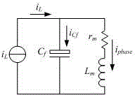
[0077] (1) Figure 5 is the equivalent circuit diagram after adding the damping resistor. Such as Figure 5 As shown, the inductor current keeps constant at the moment of commutation of the motor, which can be regarded as a constant current source, and its current value is i L . Capacitance C f It is connected in parallel with the motor phase winding at both ends of the inductance, r m is the motor phase resistance, L m is the motor phase inductance. R is the resistance value of the added virtual resistance, which is equivalently connected in parallel at both ends of the capacitor. according to Figure 5 , write the circuit equation in the complex frequency domain as follows:

[0078] i cf ( s ) . 1 Cs = u cf ...

Embodiment 2

[0094] Example 2: Buck capacitor in series with virtual resistor

[0095] (1) Figure 9 is the equivalent circuit diagram after adding the damping resistor. Such as Figure 9 As shown, the inductor current keeps constant at the moment of commutation of the motor, which can be regarded as a constant current source, and its current value is i L . Capacitance C f It is connected in parallel with the motor phase winding at both ends of the inductance, r m is the motor phase resistance, L m is the motor phase inductance. R is the resistance value of the added virtual resistance, which is equivalently connected in series with the capacitor branch. according to Figure 9 , write the circuit equation in the complex frequency domain as follows:

[0096] i cf ( R + 1 Cs ) = u cf

[0097] ...

Embodiment 3

[0109] Embodiment 3: Inverter bus bar series virtual resistance

[0110] (1) Figure 13 is the equivalent circuit diagram after adding the damping resistor. Such as Figure 13 As shown, the inductor current keeps constant at the moment of commutation of the motor, which can be regarded as a constant current source, and its current value is i L . Capacitance C f It is connected in parallel with the motor phase winding at both ends of the inductance, r m is the motor phase resistance, L m is the motor phase inductance. R is the resistance value of the added virtual resistance, which is equivalently connected in series on the inverter bus branch. according to Figure 13 , write the circuit equation in the complex frequency domain as follows:

[0111] i cf ( R + 1 Cs ) = u cf

[011...


PUM


Abstract

The invention disclosed an active damping method of a Buck circuit brushless direct current motor control system. The active damping method can be realized through the following three kinds of modes: a Buck capacitor is connected in parallel with a virtual resistor; a Buck capacitor is connected in series with a virtual resistor; and an inverter bus is connected in series with a virtual resistor. According to the active damping method, a driving system is under rotation speed and current double-closed-loop control, wherein the outer loop is a rotation speed loop which adopts PI adjuster control, and the inner loop is a current loop, wherein the current loop adopts single-period control so that inductive current can better track a given value. When the value of the Buck capacitor is small, the method can increase the damping of the control system, and stabilize the output voltage of a Buck bus fast in a phase converting period, and therefore, motor phase current can fast recover a steady-state value in the phase converting period, and current resonance can be inhibited. A damping effect is realized through the control algorithm of the system, and the damping of the system can be effectively increased under the premise that system loss is not increased, and the resonance of the motor phase current can be suppressed, and the stability of the control system can be improved.

Description

technical field [0001] The invention relates to an active damping method for a Buck circuit brushless DC motor control system, belonging to the field of DC converter-motor drive. Background technique [0002] The rotor of the brushless DC motor is excited by permanent magnet materials. Due to its small size, high power density, strong dynamic adaptability, and easy control, it has been widely used in various fields of production and life. However, the speed regulation range of brushless DC motors under various traditional PWM control methods is limited by the frequency of the switching tube of the inverter, and high-frequency PWM chopping will greatly increase the switching loss. [0003] With the development of power electronics technology, Buck circuit is more and more used in the occasion of motor speed regulation. The output voltage of the Buck circuit can be adjusted by controlling the duty cycle of the switching tube, which is very suitable for some occasions that req...

Claims


Application Information

Patent Timeline
Patent Type & Authority Applications(China)
IPC IPC(8): H02P7/28
Inventor 单涛王晓琳倪拓成
Owner SUZHOU SEIDAL INTELLIGENT TECH CO LTD
Why Eureka
Try Eureka